Stickman393
Well-known member
I've got this pedal on my bench right now. Picked it up cheap because it was broken.
Someone clearly used the wrong power supply on this thing at some point: there's a little step-up, dual voltage transformer in there, and the primary reads as a short. Like...more of a short than would be typical. Barely any voltage on the secondary.
Soooooo...I need to figure out how to replace this little thing. Easy enough if I can figure out what voltages it originally operated at...but I need to use the schematic in order to find some clues.
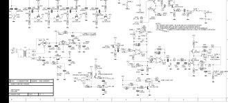
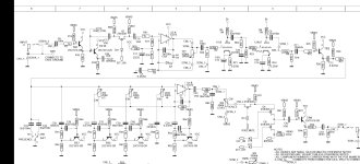
The original power supply was a 12vac. From there it goes directly to the primary coil of this little "TUBE-A FEDERAL" transformer. I do not believe I'm going to be able to find a direct replacement for this thing, so I have to improvise.
Looking at the schematic, and from what I've read online: it's a step up transformer with a slightly higher voltage tap and a much higher voltage tap.
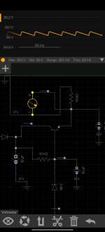
The lower voltage tap goes off to a 33 ohm resistor to the tube heater filaments (I imagine in series, though I'll double check) and a 78L12 12V regulator. The higher voltage tap goes off to some kind of poor man's half wave rectifier/ 96vdc regulator. So...my first assumption here is that the first tap is in the 15-18V range, and my second tap is in the 100+ volt range. Could one of the electrical gurus here double check me on that?
IF THAT IS THE CASE...then I have the following that I'm kicking around as an idea to get this thing working again:
Let's just say I run a single 15-16VAC wall wart transformer, probably around 2VA, into the pedal, using that for the low voltage section.
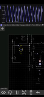
THEN, I would use something like a 120/20VAC transformer wired in in back-to-back configuration, with one leg on the primary and secondary jumped to create a common leg between them. That *should* induce a roughly 100vac potential on the primary, right?
It seems like this should work? Sharing a common leg certainly works for autotransformers, but maybe I'm missing something...after all, it it was that simple why wouldn't ibanez have just done that to begin with? That said: I see 120Vac/24Vac all the time at work with one leg of the secondary bonded to ground...by code, neutral is bonded to ground as well. Wouldn't this be essentially the same thing?
My goal here is to recreate this dual-voltage step-up transformer with as few parts as possible.
Before the warnings, yes I understand the dangers of working with these kinds of voltages and yes I understand how to do so safely. I fuck around with 460Vac on the regular at work. But...I would appreciate some educated feedback, as this is starting to get into an area where I have questions.
Schematic attached:


Last edited:


