Svenson007
Active member
Hey guys! Luckily I don’t have to post very often here anymore. I soldered the three SMT j201’s for my Neurocyton Preamp (Greer Soma) with no problems as always. I’ve built a few before… Q2-Q4 went great with my new Hakko (love it sooo much.) BUT I ended up using a tip I’m not used to on Q1. Most of it ended up fried.
I might sound kinda silly with the following questions. But I suffer from a form of dyslexia, and it makes comprehending these things rather tough. Especially with a new problem.
I completely fried Q1 and things just got much worse from there. I made a small easily solvable mistake into quite a big deal not being patient enough.
I might have enough of the two side by side pads to solder a j201back on. But I’m not counting on it. It will most likely have to end up on the flip side of the pcb, heading to the right connections via Leeds etc.
I haven’t had to deal with mistakes with j201’s.
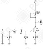
Looking at the section of the schematic below, I cannot envision the orientation of my Jfet. I’m using jfets from Pedal PCB.. so the standard pin-out. It’s the only pinout I know.
Could anybody help me with my orientation? i just need to know how a j201 fits into this circuit. I guess I’m asking which pin goes where in the circuit when it comes down to it.
If I just have a loose jfet, how would I make the proper connections? Is the signal entering the S pad on my Jfet?
Does Gate go to the biasing trim pot… and D goes to R4 and ground?
If anyone could doodle a little something onto my pic that would be KILLER. I just want to know which pin is which on the schematic and how it fits in.
I’m sure it is straight-forward, but this sort of thing throws me for a spin sometimes.
Thanks guys. You’re awesome.


