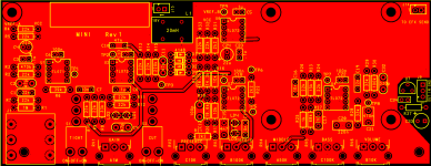
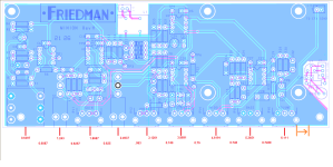
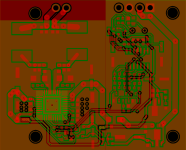
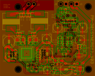
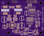
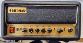
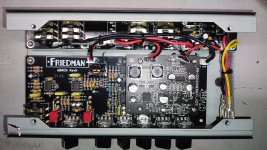
Posting this as it's a pedal with a Class D amp and FX loop.
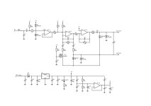
Would be nice to have a schematic created and see the difference between this and the BE-OD Deluxe and how to modify it to make it even better.
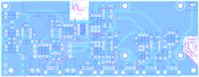
There are 3 board:
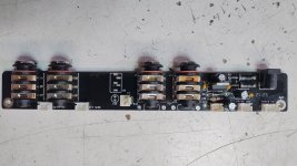
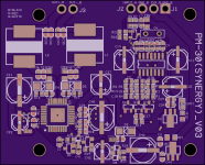
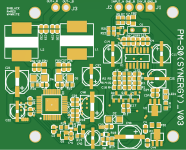
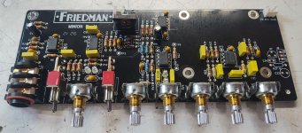
1. The Main board (this one, which is the preamp (pedal). I think the FX Loop is on it, but haven't gone thru it.
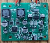
2. The Amp board (SMD)
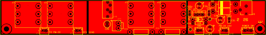
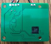
3. The Output board which has the speaker outputs and the fx loop return and send.
I will be taking apart and reversing the other 2 board, possibly this weekend.
Enjoy!
Would be nice to have a schematic created and see the difference between this and the BE-OD Deluxe and how to modify it to make it even better.
There are 3 board:
1. The Main board (this one, which is the preamp (pedal). I think the FX Loop is on it, but haven't gone thru it.
2. The Amp board (SMD)
3. The Output board which has the speaker outputs and the fx loop return and send.
I will be taking apart and reversing the other 2 board, possibly this weekend.
Enjoy!
Attachments
-
 IMG_20251230_131656804_HDR.jpg325.1 KB · Views: 90
 -
 IMG_20251230_133141139.jpg578.3 KB · Views: 90
 -
 IMG_20251231_183555090.jpg363.4 KB · Views: 86
 -
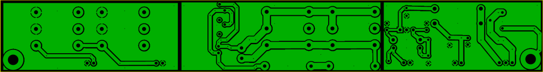
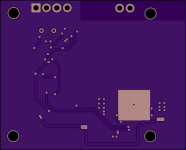
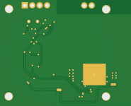
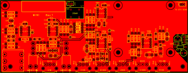 Friedman MINI - PCB (front).png241.1 KB · Views: 82
 -
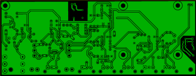
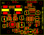
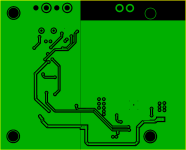
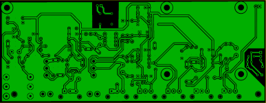 Friedman MINI - PCB (rear).png123.9 KB · Views: 75
 -
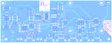
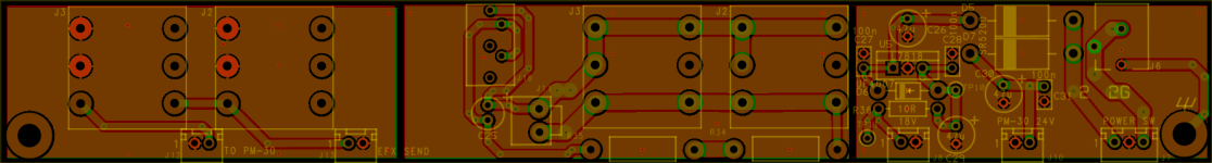
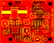
 Friedman MINI - PCB (xray).png414.1 KB · Views: 83


")