
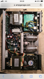
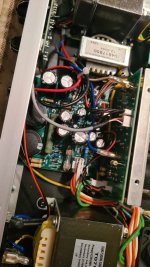
Hey gang. I want to build something like the Fryette power station but can’t find a schematic. I have been sent a picture of the internals of the device on another forum which I have attached. Would it be possible to have your help in developing or finding a schematic for this device?
You are using an out of date browser. It may not display this or other websites correctly.
You should upgrade or use an alternative browser.
You should upgrade or use an alternative browser.
Fryette Powerstation Schematic
- Thread starter M3thoms
- Start date
Harry Klippton
Not Interested
Lol not from that picture
Yeah it’s not the greatest but it’s a start, more info than I had this morning anyway.Lol not from that picture


Robert
Reverse Engineer
Someone is going to need one of these on the bench, disassembled.
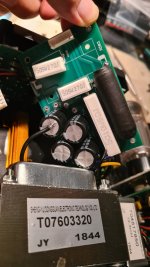
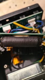
There will need to be voltage measurements, part numbers noted, etc.
@vigilante398 might have more experience with it, but I'm not even sure the visible part numbers on those transformers will be much help.
There will need to be voltage measurements, part numbers noted, etc.
@vigilante398 might have more experience with it, but I'm not even sure the visible part numbers on those transformers will be much help.
Thanks I'll reach out to himSomeone is going to need one of these on the bench, disassembled.
There will need to be voltage measurements, part numbers noted, etc.
@vigilante398 might have more experience with it, but I'm not even sure the visible part numbers on those transformers will be much help.
vigilante398
Authorized Vendor
I thought I had seen a schematic for one of these around as I was considering designing something similar, but now I'm having trouble finding it.
If you're looking to build your own then you will of course need a full schematic, and there's no reliable way to get that from pictures. If I were doing a trace I would need to be able to move things around, check continuity to verify electrically what I see visually, and potentially remove components to see what's going on underneath (not always necessary, but happens sometimes).
EDIT: removed some stuff that had already been answered but my brain skipped over on first read.
I can also guarantee that once traced out, and suitable iron and other parts sourced, he won’t save any $$ building vs buying.I thought I had seen a schematic for one of these around as I was considering designing something similar, but now I'm having trouble finding it.
If you're looking to build your own then you will of course need a full schematic, and there's no reliable way to get that from pictures. If I were doing a trace I would need to be able to move things around, check continuity to verify electrically what I see visually, and potentially remove components to see what's going on underneath (not always necessary, but happens sometimes).
If you can find the schematic that would be awesome. I do want to build one. But not to save money, as some have suggested, but because I have an interest in how these things work and I think by building something you really come to understand it. That helps you design original stuff and make tweaks. It’s not all about the $$.I thought I had seen a schematic for one of these around as I was considering designing something similar, but now I'm having trouble finding it.
If you're looking to build your own then you will of course need a full schematic, and there's no reliable way to get that from pictures. If I were doing a trace I would need to be able to move things around, check continuity to verify electrically what I see visually, and potentially remove components to see what's going on underneath (not always necessary, but happens sometimes).
EDIT: removed some stuff that had already been answered but my brain skipped over on first read.
That’s a good attitude, and I fully respect that! Just wanted to make sure you didn’t have the expectation to save a ton building it.If you can find the schematic that would be awesome. I do want to build one. But not to save money, as some have suggested, but because I have an interest in how these things work and I think by building something you really come to understand it. That helps you design original stuff and make tweaks. It’s not all about the $$.
One thing I’d say would be the “gotcha” points with this type of build, is heat management. The reason why a lot of the better attenuators aren’t copied is they simply would burn up if built in a normal Hammond box etc. with this one having reactive loads and another amp, the transformers would also be the gotcha point, where you would have to either compromise with off the shelf Hammonds, or have someone custom wind, which is a whole new rabbit hole (personally I’d take the Hammond “compromise” myself!).
vigilante398
Authorized Vendor
I was talking to my friend that I bounce all my ideas off of and he reminded me that the general consensus is that the power section of the Fryette D60 is the same as the main part of the Powerstation. This schematic doesn't have the reactive load (some good reading on those here) and is missing the warm/brite switches, but it will get you most of the way there. It also doesn't have the power supply, but you can generally design that yourself based on the needs of the circuit, which also allows you to scale it if you want to use different tubes. I'm partial to EL84s, so if I were to design something like this for myself I could scale the power section to be more suitable for EL84, and I can choose a 15W design or a 30W. You do you.If you can find the schematic that would be awesome. I do want to build one. But not to save money, as some have suggested, but because I have an interest in how these things work and I think by building something you really come to understand it. That helps you design original stuff and make tweaks. It’s not all about the $$.
I will of course echo the fact that this is not a trivial thing to build and will be expensive, but it will also be dangerous, please take all necessary safety precautions when dealing with high voltage. Tube amplifiers can kill you and it will hurt the whole time you're dying.

Robert
Reverse Engineer
One thing I’d say would be the “gotcha” points with this type of build, is heat management.
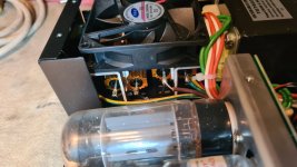
I'm always put off by fans in this type of equipment... I'm no expert on attenuators so maybe that's common in something that is designed to dissipate power?
I had an old Peavey Classic (30?) amp that had fans inside to cool the power tubes and that really just bugged the hell out of me. You couldn't really hear them when the amp was cooking, but it sounded like a little jet engine firing up when you first flipped on the power.
vigilante398
Authorized Vendor
Yup, it's common to have a fan on large attenuators and dummy loads. The powerstation uses a bank of 50W resistors for that, and they're already mounted to the chassis for conduction, but they're single-digit ohm resistors straight to ground so they're taking all the power of whatever amp you're plugging into them and they're getting HOT.I'm always put off by fans in this type of equipment... I'm no expert on attenuators so maybe that's common in something that is designed to dissipate power?
I had an old Peavey Classic (30?) amp that had fans inside to cool the power tubes and that really just bugged the hell out of me. You couldn't really hear them when the amp was cooking, but it sounded like a little jet engine firing up when you first flipped on the power.
I had a couple THD hot plates that I had over the years (used more as a bench load than attenuator, since in most amps a well designed Post phase inverter master sounds pretty much the same and is easier on the tubes/transformers). They actually had the wire wound resistive elements “cemented” into the uber-thick heat sink/enclosure ie eliminating the resistor body as a heat sink element. They also used a fan as part of the power sinking… low volumes, no fan, but the harder you drove it, the faster the fan spun.I'm always put off by fans in this type of equipment... I'm no expert on attenuators so maybe that's common in something that is designed to dissipate power?
I had an old Peavey Classic (30?) amp that had fans inside to cool the power tubes and that really just bugged the hell out of me. You couldn't really hear them when the amp was cooking, but it sounded like a little jet engine firing up when you first flipped on the power.
After seeing how they had custom resistors cemented into a custom designed massive heat sink, I knew I didn’t want to bother trying to copy it lol.
Alan W
Well-known member
As others have responded, that's the attitude that pretty much everyone here fully appreciates, so you're come to the right place.If you can find the schematic that would be awesome. I do want to build one. But not to save money, as some have suggested, but because I have an interest in how these things work and I think by building something you really come to understand it. That helps you design original stuff and make tweaks. It’s not all about the $$.
I'm gonna go out on a limb and guess that you haven't done any high voltage builds yet, (mainly from your underestimation of what info is needed to trace a circuit), and suggest that before you take on something like this, you build at least one project that has a bit more instructions to it. I'd recommend looking at Trinity Amps, and others here might have a few other suggestions. While I don't mean to scare you, there are a few techniques you need to be aware of and comfortable with before messing with higher voltage builds, as the voltage could be lethal. That's not the lesson you want to learn.
I’ve done amplifier circuits before so I’m used to taking caution with high voltage. However Ive only done stuff with turret boards, and from schematics that have been double and triple checked. Having scoured the internet for a few days and only been given photos I reached out to develop the schematic from scratch. Rest assured I will exercise caution.As others have responded, that's the attitude that pretty much everyone here fully appreciates, so you're come to the right place.
I'm gonna go out on a limb and guess that you haven't done any high voltage builds yet, (mainly from your underestimation of what info is needed to trace a circuit), and suggest that before you take on something like this, you build at least one project that has a bit more instructions to it. I'd recommend looking at Trinity Amps, and others here might have a few other suggestions. While I don't mean to scare you, there are a few techniques you need to be aware of and comfortable with before messing with higher voltage builds, as the voltage could be lethal. That's not the lesson you want to learn.
I also agree that a lower wattage power amp would be more practical, since you are looking to reduce the volume of another high powered amp. Even 10w clean power is enough to get the cops called on you and a grumpy bartender asking you to turn down!I was talking to my friend that I bounce all my ideas off of and he reminded me that the general consensus is that the power section of the Fryette D60 is the same as the main part of the Powerstation. This schematic doesn't have the reactive load (some good reading on those here) and is missing the warm/brite switches, but it will get you most of the way there. It also doesn't have the power supply, but you can generally design that yourself based on the needs of the circuit, which also allows you to scale it if you want to use different tubes. I'm partial to EL84s, so if I were to design something like this for myself I could scale the power section to be more suitable for EL84, and I can choose a 15W design or a 30W. You do you.
I will of course echo the fact that this is not a trivial thing to build and will be expensive, but it will also be dangerous, please take all necessary safety precautions when dealing with high voltage. Tube amplifiers can kill you and it will hurt the whole time you're dying.
View attachment 71477
Thanks for the schematic, what would I need to do to make a loadbox as transparent as possible?I was talking to my friend that I bounce all my ideas off of and he reminded me that the general consensus is that the power section of the Fryette D60 is the same as the main part of the Powerstation. This schematic doesn't have the reactive load (some good reading on those here) and is missing the warm/brite switches, but it will get you most of the way there. It also doesn't have the power supply, but you can generally design that yourself based on the needs of the circuit, which also allows you to scale it if you want to use different tubes. I'm partial to EL84s, so if I were to design something like this for myself I could scale the power section to be more suitable for EL84, and I can choose a 15W design or a 30W. You do you.
I will of course echo the fact that this is not a trivial thing to build and will be expensive, but it will also be dangerous, please take all necessary safety precautions when dealing with high voltage. Tube amplifiers can kill you and it will hurt the whole time you're dying.
View attachment 71477
vigilante398
Authorized Vendor
Depends on what you mean by transparent. With a load box you're typically more concerned with feel than with sound. You can use a single 8ohm 100W resistor and call it a dummy load, but it will feel stiff and uninspiring. Most higher-end boxes (including the powerstation) use a reactive load, which has an inductive element to it aside from the resistive element.Thanks for the schematic, what would I need to do to make a loadbox as transparent as possible?
A speaker is not a perfect load. It has a different impedance depending on the frequency of the input signal. A resistor, on the other hand, has the same impedance regardless of the input frequency. The goal of a reactive load is to mimic the imperfect response of a speaker for a more natural feel.
Now how important this is will depend on your use case; if you're going to be using the external power amp to drive speakers and that's the only use for it then you may not notice much of a difference. But if you're going to a direct out for recording or through headphones, you'll notice a different feel.