Gauss drive is driving me $&@!!*# insane.

TheHammer1982

Well-known member
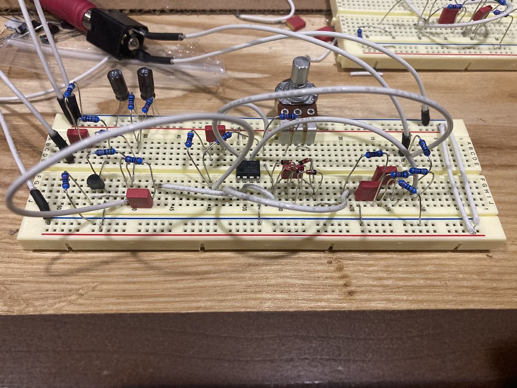
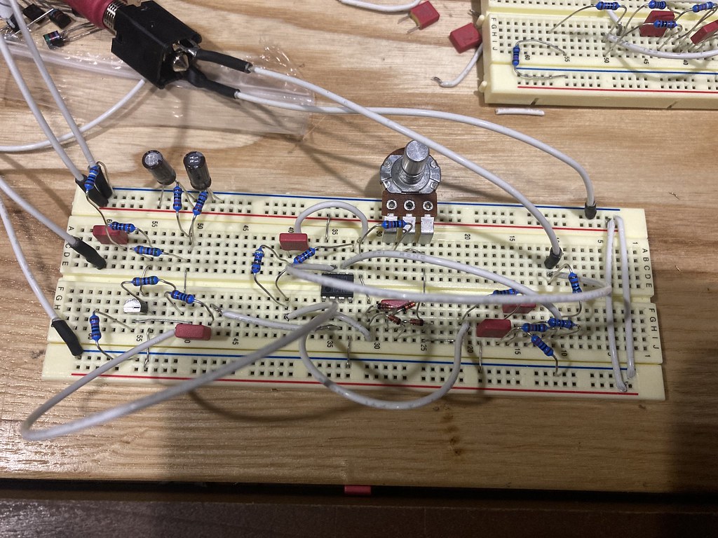
I’m attempting to breadboard the Gauss drive and it’s whipping my ass like I own it money. I can’t get past the first wiring up the first IC because I can never get the gain pot to work. The first couple of times I kept the board neat and tidy. At this point I said screw and let the rats nest fall where they man. Any ideas what I’m doing wrong?

52042645132_c7d355a3d7_b.jpg


52042646292_8e5314dbac_b.jpg
 
It’s difficult to see, but IC1.1 pin 1 should go to gain pot 2 and 3. Is that happening?
 
It looks like Pot 3 is in row 25 and IC 1 is in row 36 on the bottom of the picture. But I can’t see how they are connected.

That IC 1 node is a big one, it connects to R8, D2, D3, C3, and pot 2&3.

Edit: I think I see that it is connected.
 
Last edited:
Here’s my $0.02 for breadboarding. Edit: I haven’t taken a look at your breadboard layout since 99% of breadboards look a mess including my own. I’d rather teach you how to fish than give you a fish 😝

If you’re having trouble getting past the first IC it obviously means something’s not connected correctly. You’ll have to strip that section down to its bare parts. I would remove the diodes and c3.

Do a search on here for “Buddy’s Breadboard and Circuit Design notes”. It’s almost turned into a blog at this point and has been a place to document circuit notes and ideas in my experimenting phase. Towards the end of that thread I talk about having trouble getting a Dist+ circuit to work even though I used to be able to do it in my sleep, but I eventually figured it out. I also referenced Beavis Audio’s Dist+ breadboard project to help me understand what I did wrong.

My “Troubleshooting 101” thread (I know, shameless plug here) will give you some breadboard tips. Sometimes for me certain components aren’t pushed in all the way but they look like it.

If you don’t feel like reading and rather troubleshoot on your own, try hooking up the bare circuit a different way. Once it works you can then add back the diodes and c3. Once you understand what you did wrong you won’t do it again. Troubleshooting is IMO the most frustrating but most rewarding process with breadboarding or building in general.
 
@BuddytheReow I just found your Breadboarding and Circuit Design Notes thread and will be reading through it. I had also just started reading the Troubleshooting 101 thread AFTER I made this post lol.

You aren’t lying about troubleshooting being frustrating yet also rewarding. Last year I had to learn to troubleshoot a John Deere 8520T tractor that had a DTC (diagnostic trouble code) list a mile long. We ended up obtaining the 2000+ page service manual for it and I started going over everything. That was a truly frustrating time but I eventually found all of the issues, repaired them, and the tractor is still running great with zero DTCs. It was definitely a rewarding feeling to see it fire up and operated as it should.
 
@BuddytheReow I just found your Breadboarding and Circuit Design Notes thread and will be reading through it. I had also just started reading the Troubleshooting 101 thread AFTER I made this post lol.

You aren’t lying about troubleshooting being frustrating yet also rewarding. Last year I had to learn to troubleshoot a John Deere 8520T tractor that had a DTC (diagnostic trouble code) list a mile long. We ended up obtaining the 2000+ page service manual for it and I started going over everything. That was a truly frustrating time but I eventually found all of the issues, repaired them, and the tractor is still running great with zero DTCs. It was definitely a rewarding feeling to see it fire up and operated as it should
To be fair, having something work the first time you put it together is 5856518656654 times more rewarding than troubleshooting it.
 
  • Like
Reactions: fig
Try removing the jumper between the pins on the pot and and connect the center pin to the next node (leave 3rd pin unconnected).
 
Back
Top