z2amiller
Active member
Yep - I listed it in my guide, it's the Bouni plugin for Kicad. It lets you do the parts assignment as a separate step.KiCAD has a specific plugin I believe.
Yep - I listed it in my guide, it's the Bouni plugin for Kicad. It lets you do the parts assignment as a separate step.KiCAD has a specific plugin I believe.


Op amp wise, the only Basic I found was the TL072.
I'm not sure if by Standard, you mean in JLC Standard vs Economic

They actually used to have a basic NE555, that went away a while ago. Apparently the basic component list changes based on what they feel like carrying. I've had to change a couple of the resistors I use based on basic part changes over the years as well.I can't find a basic NE555 timer?!?
Great thread. The EOL date for Eagle has been looming, and I have wanted to learn SMDA so I took the plunge into EasyEDA. 2 weeks in, I've got most of it figured out.
For Q-tune, I've been able to take the thru-hole design in Eagle, and (starting from scratch), re-create an SMDA version in EasyEDA. It took some learning, but EasyEDA is absolutely easy. I highly recommend it, integration with JLC is cake.
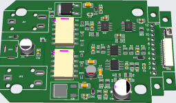
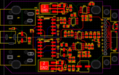
See Q-tune 4-layer SMD version, I got everything SMDA except the 3 jacks on the left. For example, the thru-hole PCB's cost about $1, and SMDA will cost about $7 each. But I'll save more than that on the components, so it's a win. AND 90% of it is assembled.
View attachment 103068
View attachment 103069
Based on the info in post #1, I need to look into a few things:
- 0603 resistors instead of 0805
- SOP-8 instead of SOIC-8 for op amps (SOP-8 is a little bigger though)
- Review all my cap selections. I found a 100n C0G/NP0 (1206) for audio. But I need to check the rest.
No the 3 electrolytics are extended but still economic not standard. The only thing that tripped me over to standard was assembly on both sides. Initially I wanted the 12-pin JST on the bottom, but it increased the cost a lot. So I found a way to put it on top and keep it economic top side assembly only.So the electro caps didn't bump you over to standard?

I've seen inconsistency there. Most of my stuff is standard anyway, but every now and then I have a design I think can be economic and the electros bump it to standard, where other times they don't. Not sure what the actual rule is.So the electro caps didn't bump you over to standard?
I've seen inconsistency there. Most of my stuff is standard anyway, but every now and then I have a design I think can be economic and the electros bump it to standard, where other times they don't. Not sure what the actual rule is.
How about clearance specs? I’ve been using .254” as well for signal and just used the same spec for minimum clearance but i wonder if it can safely go tighter?I did some digging on trace width. For signals, the default of 0.254mm (0.1") is completely adequate. Even for power that's probably fine. I did some calcs with 150 mA of current on an internal layer (hotter), and it only requires a trace width of 0.05 mm. 150 mA is a lot of current for most pedals - it is the current draw of the esp32 screen we use on Q-tune. Now practically if space allows, making the power traces wider can't hurt. On a 4-layer board where an inner layer is only for power, there's plenty of room.
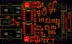
Below picture, power in green, signal red/blue:
a) kept the signal traces at 1/4mm
b) widened primary power leads to 3/4mm
c) widened the secondary power (after regulators, etc) to 1/2mm
d) notice the added vias on the ground in the regulators. I've been told, more vias the better, pretty much everywhere.
I think the above is completely overkill, but so easy, why not.
View attachment 103084
I assume this logic applies to clearance between traces/pads and the ground pour as well? I try to keep traces and pads well away from each other when possible… SMT is a very different animal from laying out a through hole board in that regard for sure though.Creepage depends on what the trace is carrying. You have creepage required for safety against arcing (purely voltage related and below 9V you can go really tight) but then there is creepage that is specific to coupling between signal. Then you should take into a count not only the voltage difference but impedance. And also looping issues when you have one trace and “it’s ground return” too close.
I am more into amps when it comes to guideline for this but: know what each trace actually is, have a set of conservative rules for general tracing and don’t be scared of using necks here and there for safety. Better a neck than an arc or coupling!
Please elaborateYes same for ground pours. And keep in mind good grounding practice - not all grounds traces are equal, even if they end up tied at the same spot.
Long story short, and to my limited understanding: ground that have to do with power require higher current and see more electron movement. It's not the case for most signal grounds. If your audio ground "draws" from a power ground directly and frequently, you will end up seeing ripple from the power in your audio signal.Please elaborate
Hmmm. I suspect any EE will strongly disagree with this method. But I’m not knowledgeable enough to explain why. I’d suggest posing this question over on AAC.Long story short, and to my limited understanding: ground that have to do with power require higher current and see more electron movement. It's not the case for most signal grounds. If your audio ground "draws" from a power ground directly and frequently, you will end up seeing ripple from the power in your audio signal.
Basically, ground plane, sure, but avoid a ground plane for power and just sticking your audio ground pads on top. Although that might apply more to high power stuff (ie tube amps or pedals with heaters) than regular 9V pedals. Fwiw I trace my PCBs with buses and generally only use pours around bridge rectifiers and filter caps.
