You are using an out of date browser. It may not display this or other websites correctly.
You should upgrade or use an alternative browser.
You should upgrade or use an alternative browser.
Green Sreamer
- Thread starter OD is Glorious
- Start date
OD is Glorious
Well-known member
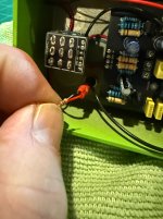
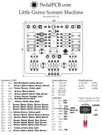
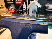
Thanks all! I made a build report for this pedal. The one issue with my pre-wired LED from Love My Switches is that they prewire them with a resistor. Extremely convenient for most purposes but apparently not for a clipping light. When the light needed aggressive high gain and everything turned up I remembered they prewire with resistor so i removed it and now the light works as intended. I am sorry if I overpost here. I think as a new person involved in the hobby I need so much guidance.
Attachments
OD is Glorious
Well-known member
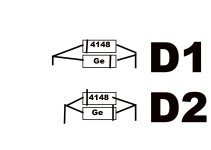
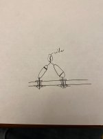
A couple images- I like to put the color codes on paper to help with installation. Also trying to nail down the diode situation. I am still unclear about how to put two diodes in each slot in order to mitigate the mid hump. Like if I out them opposite in each slot D1 and D2? If I orient the two diodes in each slot facing the same direction I think it increases forward voltage? So I made a diagram to help me understand if this is what was suggested in this thread. In my example I am thinking of combining Ge and Silicone. Thanks in advanceThe bigger chunk of metal inside that clear led is the cathode (negative) (toward the center of the board). Just for reference. Glad you got it going!
Attachments
Guardians of the analog
Papi Fuego
I know you are new to this and it feels like you're grasping at straws to understand, so I'm gonna leave this hear for you, do what you want with it, but addressing the mid hump with diodes ain't the way my guy.
 www.electrosmash.com
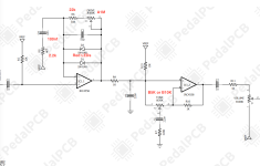
ElectroSmash - Tube Screamer Circuit Analysis
Schematic, JFET Bypass Switching, JFET Switch Operation, Toggle Circuit Operation, True Bypass Alternative,Power Supply, Input Stage, Input Impedance Calculation,Input Buffer Gain Calculation, Clipping Amp
OD is Glorious
Well-known member
That’s helpful. I will read that when I get home. But I do wanna know though is if I double diode in each slot how do I orient the negative?I know you are new to this and it feels like you're grasping and straws to understand, so I'm gonna leave this hear for you, do what you want with it, but addressing the mid hump with diodes ain't the way my guy.
ElectroSmash - Tube Screamer Circuit Analysis
Schematic, JFET Bypass Switching, JFET Switch Operation, Toggle Circuit Operation, True Bypass Alternative,Power Supply, Input Stage, Input Impedance Calculation,Input Buffer Gain Calculation, Clipping Amp
Guardians of the analog
Papi Fuego
Are you trying to double them in each slot to raise the clipping threshold?That’s helpful. I will read that when I get home. But I do wanna know though is if I double diode in each slot how do I orient the negative?
OD is Glorious
Well-known member
Somebody suggested putting two diodes in D1 and two diodes in D2. I’m trying to figure out how to do that.Are you trying to double them in each slot to raise the clipping threshold?
OD is Glorious
Well-known member
Thanks. And can I also do it the way I diagrammed? I followed this video and learned a lot but the guy never covered this. He just said two diodes and did not talk about orientation.You’ll want them in series to raise the Vf (total forward voltage. , also = clipping threshold).
OD is Glorious
Well-known member
Yes I do and I use it to test resistorsAgree about reading that article. Also, Do you have a multimeter? If not, get a cheap one and put it in Beep mode (conductivity test) to illustrate how the pcb points correspond to the circuit diagram. That process might clarify things.
OD is Glorious
Well-known member
I am rather dense and tend to develop a cursory knowledge of things and then dive in. I will need to slow down and perhaps do more breadboarding, reading and experimenting. I very much appreciate you all for your help. i am right now building another Screamer so I can try new things.

OD is Glorious
Well-known member
I appreciate you. I’m gonna use Ge diodes. I bought some of those foot switch boosters from pedalPCB. I’m thinking if I use Ge, they have a lower forward voltage and they will subdue the pedal enough that I might need to add that booster on the foot switch. At least that’s my understanding. I used a bread board with some Ge and they seem to quiet the signal a lot more than the silicone. https://www.pedalpcb.com/product/pcb633/your diagram was not correct, it showed diodes connected in parallel, not series. Also, if it helps, pretend the A & K holes aren't there. they're just for convenience so the LED fits nicer. They function just like the outer holes.
View attachment 110413
Edit: perhaps two Ge in d1 and d2 would increase the forward voltage enough that no boost will be needed.
Last edited:
Guardians of the analog
Papi Fuego

OD is Glorious
Well-known member
I love your name "Guardians of the Analog". I bought a t shirt on Amazon https://www.amazon.com/dp/B07L2SRTRZ?psc=1&th=1&customizationToken=MC_Assembly_1#B0B5B5MFZ3&customId=B0B5B5MFZ3&ref_=ppx_hzsearch_conn_dt_b_fed_configurable_asin_1
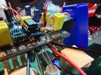
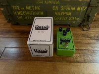
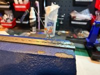
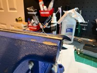
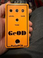
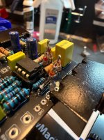
Here is what i am doing. I noticed all the little mean green screamers posted in this forum use the PedalPCB boards markings for diode direction. So D1 and D2 have the negative on the same side in D1 and D2. So following the suggestion of Phi1 I am tying two diodes together in the same direction. Oddly enough I note that these Soviet diodes stripe the positive side or anode side instead of the cathode. So I tented them like Phil said, and have not soldered yet. And here is my enclosure marked Ge OD
Here is what i am doing. I noticed all the little mean green screamers posted in this forum use the PedalPCB boards markings for diode direction. So D1 and D2 have the negative on the same side in D1 and D2. So following the suggestion of Phi1 I am tying two diodes together in the same direction. Oddly enough I note that these Soviet diodes stripe the positive side or anode side instead of the cathode. So I tented them like Phil said, and have not soldered yet. And here is my enclosure marked Ge OD
Attachments
OD is Glorious
Well-known member
OD is Glorious
Well-known member
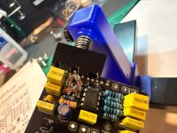
Also, I saw a thread about the TL072’s being suspect. I noticed this 4558 chip I have doesn’t have that circle dot. I ordered some more off of stomp box. Hopefully they’ll be better. I ordered two different kinds. Anyway, not sure about this chip because it looks like the one that was being discussed in the TLO72 thread.
Similar threads
- Replies
- 0
- Views
- 139