Hi there,
When building my first PedalPCB pedal, I encountered the weirdest problem - or at least this is quite weird for this beginner")
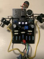
The pedal in question is the Clandestine Preamp and I’m building it from a kit I got from Musikding. Initially, soldering everything in place was easy enough, although I messed up wiring the switch at first as I expected it to be wired the same way the switch from a different non-PedalPCB kit I had just completed. After redoing the soldering on the footswitch, first I tested the pedal outside the enclosure. I only tried it for a brief moment, but noticed that led went on and that the pedal gave me the effect I expected it to: distorted tones sounded slightly smoother and everything in general a little prettier. I was so excited that I don’t think I tried adjusting the gain pot, but at least the 3-way switch had the expected effect on the tone. Also the trimpot for bias worked as expected.
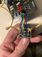
Next I stuck everything in the enclosure. It was a tight fit and I noticed that I had left some of the wires too long. Before turning the pedal on, I, again, got a normal bypass signal. Next I turned it on. The led went on, but I only got the bypass tone even with the pedal on. Turning the pot or trying different switch positions did nothing. I tried to adjust the internal trim pot, but that too did nothing.
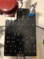
I opened the pedal and noticed that one of the wires had come partly off. That didn’t surprise me - I almost expected this. I cut the wire shorter and soldered it back. I fired up the pedal again and the same thing happened: all I got was the bypass signal regardless of whether the pedal was off or on. I opened up the enclosure and double checked everything. Everything seems fine now visually. I’ve now checked the pedal for grounding issues. The soldering could be prettier, but it should be ok. The wires should be ok too.
I’m thinking all this points to something quite specific, but being very much a beginner, I have no idea what it is. Any ideas? I’m hoping there’s a simple solution that doesn’t require me redoing everything.
I know a multimeter would help the troubleshooting, but I don’t own one yet - haven’t really had the need for one yet. I also know it would appropriate to post photos, but after struggling with the pedal for so long, I’m too exhausted to do that now (if I had any hair, I probably would have pulled some off) In any case, I can post some photos tomorrow, if requested.
When building my first PedalPCB pedal, I encountered the weirdest problem - or at least this is quite weird for this beginner
The pedal in question is the Clandestine Preamp and I’m building it from a kit I got from Musikding. Initially, soldering everything in place was easy enough, although I messed up wiring the switch at first as I expected it to be wired the same way the switch from a different non-PedalPCB kit I had just completed. After redoing the soldering on the footswitch, first I tested the pedal outside the enclosure. I only tried it for a brief moment, but noticed that led went on and that the pedal gave me the effect I expected it to: distorted tones sounded slightly smoother and everything in general a little prettier. I was so excited that I don’t think I tried adjusting the gain pot, but at least the 3-way switch had the expected effect on the tone. Also the trimpot for bias worked as expected.
Next I stuck everything in the enclosure. It was a tight fit and I noticed that I had left some of the wires too long. Before turning the pedal on, I, again, got a normal bypass signal. Next I turned it on. The led went on, but I only got the bypass tone even with the pedal on. Turning the pot or trying different switch positions did nothing. I tried to adjust the internal trim pot, but that too did nothing.
I opened the pedal and noticed that one of the wires had come partly off. That didn’t surprise me - I almost expected this. I cut the wire shorter and soldered it back. I fired up the pedal again and the same thing happened: all I got was the bypass signal regardless of whether the pedal was off or on. I opened up the enclosure and double checked everything. Everything seems fine now visually. I’ve now checked the pedal for grounding issues. The soldering could be prettier, but it should be ok. The wires should be ok too.
I’m thinking all this points to something quite specific, but being very much a beginner, I have no idea what it is. Any ideas? I’m hoping there’s a simple solution that doesn’t require me redoing everything.
I know a multimeter would help the troubleshooting, but I don’t own one yet - haven’t really had the need for one yet. I also know it would appropriate to post photos, but after struggling with the pedal for so long, I’m too exhausted to do that now (if I had any hair, I probably would have pulled some off
) In any case, I can post some photos tomorrow, if requested.