MadBean Kompromat- voltages off, weak compression - help appreciated

mkstewartesq

Well-known member
(edit to add - sorry the numbers on the voltage table run together- it looks properly spaced when composing and even now when I went to edit, but when published they run together - so I've separated the spec from myactual by a comma)

Well, after a good run of builds where it either worked straightaway or had an issue I could quickly diagnose and fix, my streak has ended. I'm stumped on this one.

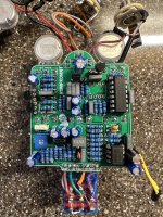
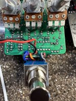
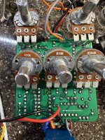
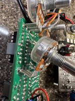
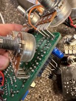
MadBean Kompromat, part of a 2-in-1 build with a General Tso. I note this because, in the pictures, you can see that it shares a power jack with another pedal (the Tso) but I keep inputs and outputs separate until Ive tested each build to verify it. The Tso works fine, and the only thing the two boards currently share is the power jack. ( If the output jack looks weird (black cable), it's because I am using a shielded cable there, with the sheath grounded to the sleeve (along with the ground wire running from the sleeve to the ground on the board. The current input isn't shielded because I will remove it when I combine the two pedals where the Tso input will be shielded.)

Since the Kompromat is a mix of the Keeley and a Barber Tone Press, I expected more compression. I see that my voltages on the IC are fairly spot on in some cases, and off in others. For at least two pins on the LM13700, I get ZERO or near-zero readings. I'll list the expected voltages along with my actual below. (note that the empty space in the board is for a CA3080 , which is not used in this build if the LM13700 is used). I'm also getting some weird phasey sound as a note decays if I turn the attack knob (top row, far right) fully counterclockwise. So something is up somewhere.

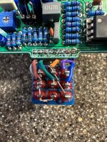
Pictures attached, Because the pots are installed, I tried to bend them back to give a view of the board joints hat would otherwise be obscured. Schematic also attached.

Any help appreciated. Thanks in advance.
Mike

Voltages MadBean Spec Mine
IC1 (CA3080) OMITTED

IC2 (TL072)
1 4.59 , 4.36
2 4.72 , 6.36
3 4.57 , 4.23
4 0 , 0
5 4.58 , 4.26
6 4.58 , 4.36
7 4.58 , 4.38
8 9.18 , 8.7

IC3 (LM13700)
1 1.2 , 1.3
2 2.11 , 0.68 (sometimes 0)
3 4.6 , 3.3
4 4.6 , 3.7
5 2.5 , 3.7
6 0 , 0
7 Ignore
8. 1.84 , ZERO (no reading at all)
9 Ignore
10 Ignore
11 9.18 , 8.71
12 Ignore
13 Ignore
14 Ignore
15 Ignore
16 Ignore

Q1 (2n3904)
C 7.64 , 7.16
B 2.06 , 1.34
E 1.54 , 1.49

Q2 (2n3904)
C 7.02 , 5.1
B 2.72 , 3.76
E 2.15 , 3.64

Q3 (2n3904)
C 8.9 , 7.38
B -mv , 0
E 0 , 0

Q4 (2n3904)
C 8.9 , 7.36
B -mv , 0
E 0 , 0

Q5 (2n3904)
C 9.18 , 8.71
B 8.9 , 7.3
E 8.47 , 7.78
 

Attachments

  • Kompromat SCHEM.gif
    Kompromat SCHEM.gif
    91.6 KB · Views: 20
  • KOMP1.jpg
    KOMP1.jpg
    776.1 KB · Views: 21
  • KOMP2.jpg
    KOMP2.jpg
    563.8 KB · Views: 15
  • KOMP3.jpg
    KOMP3.jpg
    626.3 KB · Views: 8
  • KOMP4.jpg
    KOMP4.jpg
    592.6 KB · Views: 5
  • KOMP5.jpg
    KOMP5.jpg
    521.4 KB · Views: 7
  • KOMP6.jpg
    KOMP6.jpg
    486.6 KB · Views: 14
Recheck all your resistor values, I had some similar issues with this circuit,turned out I used a wrong value on accident, swapped that out and was all good, rechecking values is one of my first steps when I encounter a problem, and there is really no reason to socket transistors in this circuit, sip sockets can sometimes cause more issues than they solve.
 
An audio probe is really helpful in sniffing out problem areas if you've got one. If you don't building one is pretty simple.
Be Recheck all your resistor values, I had some similar issues with this circuit,turned out I used a wrong value on accident, swapped that out and was all good, rechecking values is one of my first steps when I encounter a problem, and there is really no reason to socket transistors in this circuit, sip sockets can sometimes cause more issues than they solve.

Thanks to both.

@peccary - I do have an audio probe but I’ve only ever really used it where the circuit was giving no output (i.e., where I can check at which point I stop hearing any audio) so I’m not sure exactly how I would use that to diagnose this issue, but it’s a good idea and I’ll give it a try.

@Paradox916 - I’ll re-check the resistors. I double checked before I installed them that they were the proper value but that doesn’t mean that there isn’t an issue somewhere/something is out of spec, because obviously something is causing weird voltage across the board. I ordered a new multimeter because my current one seems to max out at 2M Ohms and there are resistors on this board I would need to check that are above that value - and when I checked other resistors I was getting weird but consistent wrong readings that made me wonder if there might be an issue with my multimeter. So once that arrives I’ll sweep through all of the resistors again. Hopefully none of them are bad because I always find it a bear to desolder resistors on a crowded board but, again, it seems like the right thing to check so I appreciate the input.

Mike
 
You can follow the signal through the schematic and listen through each component. Even if you don't know what should be happening exactly, you can usually hear when there's something like a significant volume drop, or noise being introduced, or the like.

If you find something suspect, post here and people smarter than myself may be able to let you know what's going on. Multiple people here have built this successfully and chances are that it's builder error (it is 99% of the time) so I'm sure you'll be able to suss out the issue here.
 
So I ran through it with an audio probe – no obvious issues (with respect to the weird distortion as notes decayed, that seemed to be most noticeable around the Blend pot but I was able to bias it out). Double checked all of the resistors with a multimeter – some did not read to their expected values but I’m aware that checking a resistor that is soffered into the circuit may give different than expected readings. So I disconnected a few from the circuit and, sure enough, they all read to the value they should. so I expect similar results with the other few that are reading out of spec currently and do not plan to snip each and every one out. I do have a question about that, below.

So I’m a bit stumped. Everything checks out, but the voltages are still off as in my original post, and, while I’m getting some compression, it’s not what I was expecting and not typical of the sound of a Keeley or Barber, which the PCB is based on

My question - I do know that attempting to test a resistor that has been soldered to the board will sometimes yield inaccurate results. One of the most concerning to me was R1, which is a 4.7M resistor - when I tested it soldered to the board, it was showing a resistance of close to zero. When I snipped it out and checked the resistor, it was operating right at 4.7M. Similarly, when I put a new 4.7 M in, the resistance rating againdropped to about zero once it was installed in the board. I know that there will be some difference in resistance when the resistor is put into the board (in certain contexts) what does a drop from 4.7 million to zero seem expected?

Mike
 
I will be honest with you, I have never had to remove a resistor to check it’s value, there are a couple of situations that could account for such results as intermittent readings; problems with or a cheap meter, not setting the meter correctly, flux on the board not allowing a proper connection of the meter, or a short to ground like a possible solder bridge, ect , R1 goes straight to ground so there is no reason you shouldn’t be able to get a proper reading right on the board.
 
Just out or curiosity, are you using single coil or humbuckers? In my experience, the kompromat, is a little more subtle. You may have to run a hotter signal into it.
I’ve been testing it with my telecaster since that’s the guitar I really wanted a squashier compressor for. Before I built this two n one pedal, I actually tried a Keeley compressor side-by-side with a Thorpy Fat General (the underlying pedals that the two PCBs are based on) and the Keeley compressed a lot harder than the Thorpy, which was more subtle. Now that I put the two I built together, the General Tso actually sounds a little squashier.

Still no idea why my voltages are off on the Kompromat – I have to think that has some effect on the sound. Especially since MadBean’s documentation said that, and his experience, the LM13700 chip seemed to compress a bit more than the original CA3080.

Mike
 
I will be honest with you, I have never had to remove a resistor to check it’s value, there are a couple of situations that could account for such results as intermittent readings; problems with or a cheap meter, not setting the meter correctly, flux on the board not allowing a proper connection of the meter, or a short to ground like a possible solder bridge, ect , R1 goes straight to ground so there is no reason you shouldn’t be able to get a proper reading right on the board.
Thanks – sorry I missed this message earlier. Yes, it was very odd – I had about six resistors on the board that would not give me a proper reading while soldered in and, as I noted, when I removed a representative sample of them, all of the resistors themselves were actually fine. I can’t say that doesn’t indicate a problem here that I am not seeing, but when reading up on testing resistors, most articles I read said that you could get inaccurate reading if it was still connected to the circuit, and when I searched that topic on this board, the only thread I could find gave the same advice. So I’m not an expert enough to know what’s going on here, and you may very well be right that there is some other issue, but that was just the experience I was having testing a few resistors. All the others were showing correct readings when tested straight from the board.

Mike
 
Thanks to both.

@peccary - I do have an audio probe but I’ve only ever really used it where the circuit was giving no output (i.e., where I can check at which point I stop hearing any audio) so I’m not sure exactly how I would use that to diagnose this issue, but it’s a good idea and I’ll give it a try.

@Paradox916 - I’ll re-check the resistors. I double checked before I installed them that they were the proper value but that doesn’t mean that there isn’t an issue somewhere/something is out of spec, because obviously something is causing weird voltage across the board. I ordered a new multimeter because my current one seems to max out at 2M Ohms and there are resistors on this board I would need to check that are above that value - and when I checked other resistors I was getting weird but consistent wrong readings that made me wonder if there might be an issue with my multimeter. So once that arrives I’ll sweep through all of the resistors again. Hopefully none of them are bad because I always find it a bear to desolder resistors on a crowded board but, again, it seems like the right thing to check so I appreciate the input.

Mike
Here is a Resistor calculator.
the most common mistake is the 4th Band Multiplier ie 47, 4k7, 47K, 470K
Click On Bands for 5 Colours:
 
Here is a Resistor calculator.
the most common mistake is the 4th Band Multiplier ie 47, 4k7, 47K, 470K
Click On Bands for 5 Colours:
Yes, thank you, actually I use that on every build now – I keep my computer open next to my workstation and each time I pull out a resistor I double check the bands on that site just to make sure that I haven’t grabbed an wrong component by mistake. My potential downfall, and what I was checking when I went through the board, is that I don’t go that extra step and actually check each component with a multimeter to make sure it’s not defective before I solder it. So that led to my concern that, even though the bands were accurate, there might have been a problem with the resistors themselves due to poor quality control. But so far, that hasn’t been the case.

But that site has saved me at least once, when I used it and discovered right before soldering that I had grabbed a 4.7 resistor rather than a 4.7 K resistor.

Mike
 
1. Can you confirm as you have no knobs on your Pots that you got these Voltages with the Pots at 12 O'clock/ Half Way?

2.Did you do this listed below:

View attachment 49440
Confirmed as to all. (To be safe, I actually put knobs on the pots when I was checking the voltages to make sure I was duplicating the proper conditions. Since some of the knobs are set differently when biasing, I also wanted the knobs on to be sure I was setting them properly for the bias condition.)

Thanks for being willing to help out with this.

Mike
I live in Australia, & I have access to CA3080E & have some!
Looking at the Schematic, LM13700 Pin 8 doesn't connect on the PCB so the Voltage is within the chip itself!???
 
Last edited:
Back
Top