Magnetron Delay troubleshoot

u439857293874

Active member
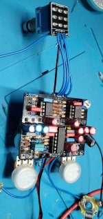
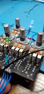
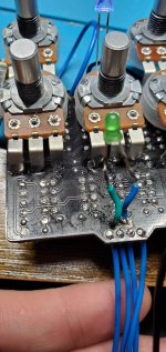
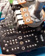
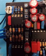
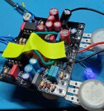
This was one of my first builds I'm trying to get working. Just redid the wiring but I'm not getting the effect. I'm going though the schematics but I'm a little unsure how to read it.

Should I have sound on both sides of R2 and R3?
R10 I'm not getting anything at all.

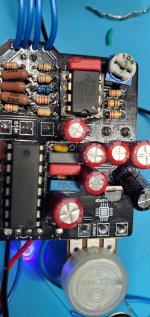
On the PT2399 chip I can hear the delay happening on one of the pins and on R25/R26 but R11 and R14 sound like the bypassed signal. Any help would be greatly appreciated, thanks!
 

Attachments

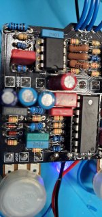
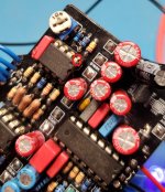
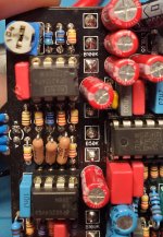
  • signal-2023-03-21-174811_002.jpeg
    signal-2023-03-21-174811_002.jpeg
    332.9 KB · Views: 13
  • signal-2023-03-21-174807_005.jpeg
    signal-2023-03-21-174807_005.jpeg
    295.6 KB · Views: 14
  • signal-2023-03-21-174807_004.jpeg
    signal-2023-03-21-174807_004.jpeg
    348.2 KB · Views: 14
  • signal-2023-03-21-174807_003.jpeg
    signal-2023-03-21-174807_003.jpeg
    308 KB · Views: 14
  • signal-2023-03-21-174807_002.jpeg
    signal-2023-03-21-174807_002.jpeg
    298.3 KB · Views: 13
This was one of my first builds I'm trying to get working. Just redid the wiring but I'm not getting the effect. I'm going though the schematics but I'm a little unsure how to read it.

Should I have sound on both sides of R2 and R3?
R10 I'm not getting anything at all.

On the PT2399 chip I can hear the delay happening on one of the pins and on R25/R26 but R11 and R14 sound like the bypassed signal. Any help would be greatly appreciated, thanks!
Looking at the schematic, the basic audio path goes straight across the top. So yes. R2, 3 opamp pins and gain pot.
 

Attachments

  • EE884905-622D-4F31-86F9-242D0C63110E_4_5005_c.jpeg
    EE884905-622D-4F31-86F9-242D0C63110E_4_5005_c.jpeg
    66.4 KB · Views: 12
Replaced R2 and R3 still the same. R3 sounding quiet. Nothing on the gain and I'm only getting audio from one of the pins in IC1 (the one in red).
 

Attachments

  • signal-2023-03-21-192254_002.jpeg
    signal-2023-03-21-192254_002.jpeg
    334.1 KB · Views: 5
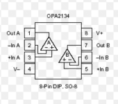
Yes I'm getting clear audio from pin 1 also from pin 7 but it's a little quiet. Nothing from the gain pot at all. One side of r6 has audio and one side has no audio.

I'm thinking about replacing the gain pot.

1679449967750.png
 
Took out the level pot which was probably unnecessary and broke a pad off in the process. The pot looked fine and tested to the right resistance so I put it back.

No sound in the level pot at all. R6, R3, R2 only have sound on one side. C2 has sound on both R4 on one side.
 

Attachments

  • 20230321_224657.jpg
    20230321_224657.jpg
    412.5 KB · Views: 4
  • 20230321_222446.jpg
    20230321_222446.jpg
    481.6 KB · Views: 4
  • 20230321_222323.jpg
    20230321_222323.jpg
    549.9 KB · Views: 4
Last edited:
Isn’t the gain pot on this the trimmer…

if I’m understanding correctly you are getting sound but not hearing the effect. Do you have the level pot turned all the way up? The level as I recall is basically your repeats volume.
 
Last edited:
Isn’t the gain pot on this the trimmer…

if I’m understanding correctly you are getting sound but not hearing the effect. Do you have the level pot turned all the way up? The level as I recall is basically your repeats volume.
Nope, no sound at all. With an audio probe, no sound from C2 up to the opamp, but has audio on pin 1. Real head scratcher.
 
I was confusing the level pot with the gain pot. I am getting sound in the gain pot on all 3 pins. Still nothing on one side of both R2 and R3. I could add some jumpers but not sure where to put them.
 
Yes I'm getting clear audio from pin 1 also from pin 7 but it's a little quiet. Nothing from the gain pot at all. One side of r6 has audio and one side has no audio.

I'm thinking about replacing the gain pot.

View attachment 44493
if you’ve got audio coming out of pin 7 your dry signal is making it through. Not sure why you’re not hearing it…. There’s a couple components after it. Can we see some of voltages?

Also for the sake of checking audio probe the output pad and work back from there til pin 7

Also you should have audio at both pin 15 and 16 of the 2399, do you? One should be the delay signal I think 16. You’ll have to wait to hear it for however long the delay is set to.
 
Last edited:
if you’ve got audio coming out of pin 7 your dry signal is making it through. Not sure why you’re not hearing it…. There’s a couple components after it. Can we see some of voltages?

Also for the sake of checking audio probe the output pad and work back from there til

I can hear dry signal on pin7 and on the output but I think what Im hearing in the output is the bypassed signal or the ground since there is no effect. I can hear the effect coming out the of the 2399 chip and on r25 and r26. What voltages do you want to see?
 
I can hear dry signal on pin7 and on the output but I think what Im hearing in the output is the bypassed signal or the ground since there is no effect. I can hear the effect coming out the of the 2399 chip and on r25 and r26. What voltages do you want to see?
You wouldn’t hear bypassed signal at pin 7, it wouldn’t be bypass if you did. What you are hearing is the dry signal.


I think your issue then lies between the output of tbr 2399 and the level pot. Follow the audio path there.
 
I was getting the effected audio on only one side of r13 so i ran a jumper from r12 to r13 and now i can hear the effect on the output. It doesn't sound great and I'm only getting audio on pin 3 of the feedback pot. At least we're getting closer! Will try some more after work. I'm on the old version btw. Build doc says 2020.
 

Attachments

  • signal-2023-03-23-155951_002.jpeg
    signal-2023-03-23-155951_002.jpeg
    548.2 KB · Views: 4
Back
Top