SOLVED Mahayana drive losing signal at op amp

AceHyzer

New member
Hey all,

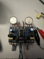
I have been working on a Mahayana Drive build. I’ve tested continuity everywhere it should be expected and as far as I understand the voltages are correct as well.

I’ve tried two different AD712s and an NE5532P and get the issue on all of them. Using an audio probe, I get signal up to pin 3 of the op amp and nothing beyond

Op amp voltages
Pins:
1,2,6,7, and 8 - 4.42V
3 - 4.25V
4 - 0V
5 - 8.86V

All legs of both mosfets are between 4.3 and 4.5V

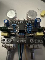
I’ve checked and rechecked solder joints, continuity, measured pots, tested the Mosfets with my DCA75, I just can’t figure out why the signal isn’t making it past the opamp input.

Any ideas? Thanks!
 

Attachments

  • IMG_2205.jpeg
    IMG_2205.jpeg
    309.6 KB · Views: 8
  • IMG_2204.jpeg
    IMG_2204.jpeg
    363.2 KB · Views: 8
  • IMG_2203.jpeg
    IMG_2203.jpeg
    318 KB · Views: 8
did you sub BS170 for the 2n7000 by any chance? Also it’s probably lighting but that 470k resistor looks off.

Test continuity based on the schematic of the whole section going from pin 2 to pin 1 of the opamp, sounds like something is shorting out or off there
 
did you sub BS170 for the 2n7000 by any chance? Also it’s probably lighting but that 470k resistor looks off.

Test continuity based on the schematic of the whole section going from pin 2 to pin 1 of the opamp, sounds like something is shorting out or off there
Thanks for the quick reply. I did not sub BS170s, I used 2 2n7000s. Also double-checked the 470k resistor and it was the lighting, it checks out. Measured it with the multimeter to be sure and it came out at 471k.

I've just checked continuity for every component between pin 2 and pin 1, everything is checking out as expected.
 
The voltages seem odd. I would expect 8 to be 9V. Out of curiosity does it work if you pull the Mosfets? The resistors all seem right. The caps I can’t really check. Otherwise i would wonder if maybe there is a component leg or something running to positive somewhere it shouldn’t.
 
🤦‍♂️Rookie mistake, I measured them correctly and wrote them down backwards on 5-8:
updated Op amp voltages
Pins:
1,2,5,6, and 7 - 4.42V
3 - 4.25V
4 - 0V
8 - 8.86V

Mosfet voltages:
Q1
D - 4.42V
G - 4.42V
S - 4.30V

Q2
D - 4.42V
G - 4.42V
S - 4.32V

Tried pulling the Mosfets, no signal past pin 3 still.
 
Haha for real though. I'm pretty baffled by this one.
I have two different testing rigs, one from fuzzdog I believe it's called "the simple tester", and an auditorium from pedalpcb. I've tested several circuits on both, so I know it's not the testing rigs. I also hooked this board up to both to make sure something hadn't gone funky there. I'm stumped!
I measured all the pots, they're measuring correctly and I got continuity on them as well. I just checked to make sure the traces to the 2n7000s were as expected and everything looks right to me and I'm getting continuity as I would expect there as well.
 
Back
Top