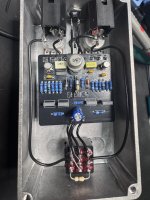
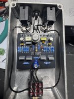
SOLVED Marigold help

swelchy

Well-known member
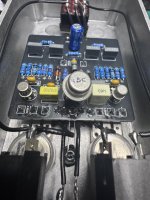
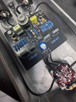
At my wits end with 2nd attempt… built completely stock specs basically
Q3 is NPN MP38 70 hfe with about 200 leakage
Used a 5.1 V zener
I’m getting about 4.2 at Q1 collector
I’m getting about 3.6 at Q2 collector
I’m getting zero voltage at Q3 collector
I’m not getting voltage at the zener either
The pedal is passing signal bypassed and engaged but the volume drop is crazy… no volume but the volume pot , fuzz pot and tone is doing stuff… it just has no umph…
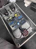
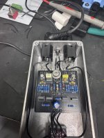
IMG_9815.jpeg IMG_9814.jpeg IMG_9813.jpeg IMG_9812.jpeg IMG_9810.jpeg
 
If you are not getting power to the zener and Q3's collector, I would suspect there is an issue in this area. I'd check continuity from C100 to R12 and R12 to R14 and D2 (Zener). The resistors, based on my review, look to be the correct values. To further prove an issue is in this area, you could audio probe after C8 and before C8. Audio after C8 and not before C8 would help localize the problem at or before the C7 and C8's juncture.
 
If you are not getting power to the zener and Q3's collector, I would suspect there is an issue in this area. I'd check continuity from C100 to R12 and R12 to R14 and D2 (Zener). The resistors, based on my review, look to be the correct values. To further prove an issue is in this area, you could audio probe after C8 and before C8. Audio after C8 and not before C8 would help localize the problem at or before the C7 and C8's juncture.
I'll do some voltage checking in a bit on it... had the exact same issue with the other board as well...
 
I have 4.7 V at the R14/R12 juncture and 2.1 V on the other end of R14.

Something is grounding your VCC. I would consider the following (in order):
  1. Confirm that you have the correct Zener and placement
  2. Make sure that none of these parts, except for the Zener is going to ground
  3. Replace R12
  4. Replace R14
  5. Replace D2
 
Any chance you took a pic of the back of one?

Two PCBs with identical bad traces are pretty uncommon... I'd be curious to see if there was any pad damage caused by the leads of that zener diode.
I have the first board I can try to clean up and post a pic… definitely weird.., but you could be right.. The zener I used does have a very tight fit on the pcb… I could have damaged the through plating installing both of them 🤷‍♂️
 
Don't tear one apart if you already have it working, I was just curious and looking for a common point of failure between the two.

A defective trace from the factory isn't impossible of course, but it's rare, and the exact same defect on two boards is even more rare.

Damaged traces seem to gravitate towards fat component leads like that. Similar to how troubleshooting threads involving dual-gang pots always ends up being the dual-gang pot shorting against something.
 
Don't tear one apart if you already have it working, I was just curious and looking for a common point of failure between the two.

A defective trace from the factory isn't impossible of course, but it's rare, and the exact same defect on two boards is even more rare.

Damaged traces seem to gravitate towards fat component leads like that. Similar to how troubleshooting threads involving dual-gang pots always ends up being the dual-gang pot shorting against something.
I'm sure your right about the odds of two in a row being bad... I did in fact feel a bit of resistance getting those leads in the hole... i bet I ripped both the traces.. it soldered up fine..... would make sense because both were bad in the same spot...
 
Don't tear one apart if you already have it working, I was just curious and looking for a common point of failure between the two.

A defective trace from the factory isn't impossible of course, but it's rare, and the exact same defect on two boards is even more rare.

Damaged traces seem to gravitate towards fat component leads like that. Similar to how troubleshooting threads involving dual-gang pots always ends up being the dual-gang pot shorting against something.


So, this may explain an experience I had with another board. Like this one, the power was lost at the diode. I could see that the trace was present, but I couldn’t understand why there was no continuity. A broken trace from the fat diode would explain it.
 
Confirmed…. I cleaned up the other pedal that I couldn’t get working and desoldered the diode… The pads were in fact compromised by me… it was a tight squeeze plus I’m a bit heavy handed on the heat… I solder @ 400C so I likely comprised both PCBs with a fatty lead leg and then clocked both of them with hot lava..
 
Back
Top