Minnow whistle (solved) and ticking on bypass but volume drop when turned on.

andare

Well-known member
I just finished building a Minnow. Definitely the most complex out of all the 8 pedals I've built so far but it worked right away. Everything seems to work as intended but I have 4 issues, 1 of which I've been able to solve:
  1. Whistling on bypass. This is due to IC2 being close to the output tip wire. Keeping this wire on the other side of the enclosure greatly reduced the whistle. I used shielded wire but I grounded the jack with a regular wire to the PCB. I suppose that defeats the purpose? Anyway I built a shield for IC2 using electrical tape and adhesive copper tape and grounded it to the output jack sleeve. Thanks to @Kinski for the idea! The whistle is gone.
  2. Ticking on bypass when S/H mode is selected. This is caused by the always-on Speed LED. I don't know how to mod the pedal so the LED is turned off on bypass. The Speed knob is enough visual feedback for me. Is there a way to short the LED or should I just cut off one leg to disconnect it?
  3. The pedal is well below unity volume in both modes.
  4. The Filter mode has low sensitivity, I really have to dig in to get the filter to react. Might be connected to #3.
    S/H mode works fine (Ship Ahoy!) though I might fine tune the trimpots once more.
I checked all my solder joints before adding the pots, double checked the pot solder joints, checked that everything that should go to ground goes to ground. At this point I don't know what else to check.

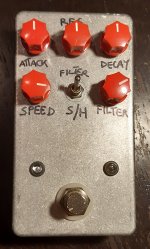
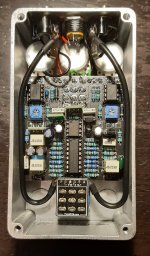
Here are pics of my low-rent build:
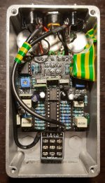
Minnow front.jpg Minnow guts.jpg Minnow shield.jpg

Thanks in advance for any help you can provide and I hope this post is helpful for future builds.
 
Does the ticking go away when you remove the LED from the circuit? How do know that it is being caused by the LED?
You should have unity volume in both modes. The filter mode on this is one of the smoothest and easy going filters out there. I suspect voltages are in order.
 
Does the ticking go away when you remove the LED from the circuit? How do know that it is being caused by the LED?
You should have unity volume in both modes. The filter mode on this is one of the smoothest and easy going filters out there. I suspect voltages are in order.
Keep in mind I'm a total noob so bear with me if I say/do silly things.

I think it's the LED but I'm not sure. Short of desoldering it I don't know how to take it out of the circuit. Shorting the anode to ground didn't turn it off. Maybe it's the LFO (if it's an LFO that causes the effect)? I tried moving the wires from the input and output jacks away from the rate LED but no dice.

As for the volume drop, the way I understand it, if there's a volume drop it means some of the input signal is being leaked to ground. That would also explain why the envelope filter only reacts to loud playing, not enough signal going in.
But I don't know what to check. I can sort of follow the schematics but I get lost easily.
How do I check for voltages?
 
Last edited:
So I took the PCB out and checked my solder joints. I reflowed a few that looked iffy. I wonder now if cleaning the PCB has weakened more joints than I can see. Unfortunately with the pots and wires in place I can't inspect any more.

Even outside the enclosure there is a difference in volume so nothing was shorting inside the box. Maybe it's just what it's supposed to sound like...

Of course the shielded wires had to snap off the breakout board!
With it soldered so close to the PCB there was no way to clean the holes. I had to solder new wires directly to the footswitch lugs which was surprisingly difficult as the solder wouldn't melt.

And for some reason the S?H now sounds worse, I had to reset the trimpots but something is missing.

What a mess! Since no one else is chiming I guess I'll call this done.
 
I’ve had one of these boards since it came out. I haven’t build it yet due to the reasons in this thread. You really have to wrestle some builds together.
 
I’ve had one of these boards since it came out. I haven’t build it yet due to the reasons in this thread. You really have to wrestle some builds together.
IMO this is a good candidate for rehousing in a bigger enclosure or at the very least I'd wire the 3PDT myself. The breakout board overlaps the PCB so I had to use 4 pieces of thin solid wire to connect it.
 
Back
Top