TUTORIAL Muroidea - Proco Rat

BuddytheReow

Breadboard Baker
Ah, the Proco Rat. Built in the 1970's and popularized in the 1980's, it can be considered a "standard" in the distortion community. This little baby can do it all: pseudo-overdrive or light distortion, distortion, and borderline fuzz territory. Due to its simplistic circuitry and versatility it has found a more permanent home on my pedalboard and hope after building one on a breadboard and modding it to your liking I hope it finds a home with you too.

First, shout out to @Danbieranowski and @Chuck D. Bones on a recent breadboard query thread I made to inspire me to do some homework and build it this morning.

What makes this pedal so great? Well, as I said it is incredibly versatile with it's gain control and the tone stack is a simple shelf filter to tweak the treble (more on that later). Not much to comment on the volume control since it just dumps the signal to ground.

Have you been following along in my other tutorials? Yes? Good, cuz now the training wheels are starting to come off with an Intermediate level breadboard build. I hope you have just as much fun as I did while putting this together. Even my wife who was working out next to me said "you look like you're having fun" as I was putting this together in my basement.

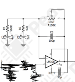
Anywho, here is the schematic and my breadboard layout. You can find the full build doc below. Shout out to @PedalPCB for having such amazing build docs as always. Stay tuned for more RAT fun!

If you take a look at the schematic it calls for a LM308. This was the original opamp used in the circuit if I'm not mistaken. You don't need the LM308 to get this circuit to work. It is rather expensive (something like $5 a pop), and there are substitutes. For my build I used a OP07, but you can also use a TL071 with one minor tweak to the circuit that I will discuss below. The OP07 and TL071 are much cheaper opamps and can be found on Tayda. If you want that magical unicorn dust, then by all means go for it! From the various youtube comparison videos out there I could barely hear the difference. The pinouts for all are the same.


1655470925567.png
1655470946880.png
 
Last edited:
Let's get that power section started!

Start with C11 and throw it in the power rails. All this does is clean up your power supply from any DC ripple.

I'm going to skip the opamp power for now since we need to layout other components first to see where we can work.

R11 and R12 act as a voltage divider and cut the voltage in half in this case. Simply google "voltage divider" if you want to learn a bit more about it, but it's a simple question of ratios between the two resistors. The connection between the two resistors is the resulting voltage. From here C12 is placed going to ground to do some more filtering just in case. This is common practice in the opamp world.

After this stage, VCC is 9v and VREF should be around 4.5v. Because of the tolerances of my components I measured 4.1v, but it works just the same in this case.

The way I breadboard power sections is to keep it pretty tight since there are few mods, if any, you can do here and want to keep the real estate for more fun tinkering;). In one column I have both resistors and the capacitor and now represents VREF!

1655473744991.png

1655473726899.png
 
Next up, the input section! It's relatively simple. Forgive the photographer on this one and his fat finger :p
1655474422847.png
My input cable is orange here and the black is ground (duh). I usually keep both power rails wired up to make things a bit simpler for me unless I need 2 separate voltages throughout the circuit, but I digress.

From input we add R1 to ground and C1 across. R1 is a pulldown resistor to adjust the impedance and kill any popping when you engage the circuit. C1 is a coupling filter, but also attenuates (I sound smart when I use that word) a lot of the lows. For many opamp distortion circuits the bass is cut out before the gain stage to reduce the muddiness.

At the end of C1 we need to add R2 which connects to VREF. This resistor helps to bias the opamp coming up. Why is this important? Well, similar to how we need to bias transistors we also need to "trick" the opamp into thinking it's getting power in it's input.

R4 is also added at this junction. We will tack on a capacitor to create a low pass filter in the next step.

1655474479584.png
 
Last edited:
Time to hook up the opamp!

First, let's finish off the RC filter mentioned at the end of the previous step (R4).

C4 is tacked on to R4, but goes to ground. This acts as a low pass filter and my calculation has the cutoff at basically 16kHz, so it gets rid of the ridiculously high highs and hiss.

For opamp builds I tend to build everything beforehand to see what kind of space I can work with. This one has a feedback loop in it (next step, not now) so I gave myself 5-10 extra columns to work with. This is just the method to my madness, but you're more than welcome to tweak it to your taste.

Let's power it up. Pin 7 to 9v and pin 4 to ground.

We then need to connect our signal to the non-inverting input of the opamp which is pin 3 here (the blue jumper in my pic).

OK. C6 connects pins 1 and 8 together. Why is this needed? If memory serves me correctly, this is needed to adjust the slew rate of the opamp. What is slew rate? Think of it as how quickly the opamp works. For the LM308 and OP07, this capacitor is needed. If you are using a TL071 this component is not necessary since it is built into the chip. The pinouts of these opamps are the same.

1655478042778.png

1655478005790.png
 
  • Like
Reactions: fig
Let's setup the feedback loop. This is the way I put this on my board, but if you can find a different way that suits your taste, by all means.

This is being broken up in 2 parts since it's a feedback loop is much quirkier than BJTs in a fuzz.
You'll see 2 sets of RC filters: R3/C2 and R5/C3. Both of these work together to essentially select the frequencies the opamp will boost. It won't work without these.

Both caps go to ground (negative side) and their resistor partners both attach to the same point (the feedback loop itself). If you're paying attention to the row numbers on my board you will see we made a pretty big jump. This is simply give us room to work and we will work out way back to the opamp. Here is where you can do one of the most popular mods, but I'll save that for later once we get this up and running. In general, start with the stock circuit to make sure it works, then tweak it.
1655486343701.png


1655486316867.png
 
  • Like
Reactions: fig
Let's finish up the feedback loop. Once it's done it will resemble this part of the schematic. Forget the scribbles.
1655486844185.png

From the pair of RC filters attach it to lug 1 of your GAIN pot. I'm using a trimmer to make a cleaner picture, but the concept is the same. You'll want to jumper lugs 2 and 3 together. You can see (hopefully) I put a small jumper between lugs 2 and 3 of my trimmer. It is white.

C5 should be installed between lugs 1 and 3 of the pot/trimmer. This is to clip out some of the hiss that may occur when the gain is cranked to max. The circuit will still work without it, but you may not like what you hear.

Lug 3 gets jumpered to pin 6 of the opamp and C7 goes from pin 6 to the next stage.
Lug 1 gets jumpered to pin 2 of the opamp. You've now closed the feedback loop to make a complete circuit.

If you're itching to see how this sounds (and it's a good idea to check at this stage to make sure the circuit is working) plug your output wire right after C7. It should sound almost, but not quite, like a RAT!

1655486738223.png
 

Attachments

  • 1655486790394.png
    1655486790394.png
    42.7 KB · Views: 12
Let's keep going and install the diodes and EQ filter. The EQ section is a simple shelf filter that @Chuck D. Bones wrote about in the Boneyard section. His explanation is much better than I could ever come up with. You can read about the shelf filter here.

1655490271359.png

We ended the last section with C7 and now we're going to tack on R6 right after it. Where R6 ends, throw 2 opposing diodes to ground. The stock schematic has 1n914 and that's what I threw in there. This is another great mod section, but more on that later.

After the diodes I threw a small purple-ish jumper to lug 1 of a pot. Lugs 2 and 3 are connected together with another small jumper, and R7 comes out of lug 3. At the end of lug 3 put C8 to ground.

We're almost there, folks!

1655490322120.png
 
Alright. 2 more steps and we're done. Now we're approaching the output buffer stage. The buffer uses a 2n5458 JFET. I didn't have a 2n5458, so I threw in a 2n5457 instead. If you don't have either just make sure it's a JFET, but check the pinouts. To my understanding when it comes to buffers the part number doesn't really matter as much as you think. Furthermore, I have no idea why an output buffer is needed! Let's ask out local circuit wizard @Chuck D. Bones . Can you shed some light on this for us? I'm no expert myself, but someday I hope to be when analyzing circuits.

1655490714137.png

Right after our shelf filter we need to add another decoupling/filter cap C9. After that I added a small jumper (red) to make a nice picture then added R8 to ground. Why is this needed? JFETs are finicky creatures and for some reason or another they need to be able to "see" ground from the gate pin. That's the only way I can explain it and really the only way it was "taught" (Google).

Throwing Q1 in there, connect R8 to gate, drain to 9v, and R9 to source pins. Again, check the pinouts of your JFET here to see if they match mine. Mine go D-S-G with the flat part facing toward me.


1655490660627.png
 
Geez Louise, I didn't think I'd ever get here. We are now on the home stretch and merely need to install the volume section before you can rock it before you box it!

1655491332663.png

2 more components and connections. Out of the source of the buffer we need to add our final decoupling cap C10. Just remember that the long pin is the positive side. Like many volume pots at the end of a circuit (but not all) lug 3 is your raw signal, lug 1 goes to ground, and lug 2 is your output.

1655491308351.png
 
Behold! The Proco Rat! I hope you had just as much fun putting this together as I did. I will work on mods next once I have a chance to try some out and see what I like and which ones don't really work.

For the record, I did know that I threw in the GAIN pot upside down just to make the picture easier so turning it CCW increases the gain and not decreases. If you're using regular pots just keep this in mind or flip flop the connector wires on lugs 1 and 3.

Happy Baking, y'all!

BuddytheReow

1655491615364.png
 
For the LM308 and OP07, this capacitor is needed.

Great post!

BTW, I learned here a while back (I think it was from Chuck) that the OP07 doesn't actually use a compensation capacitor. I used to believe it did because I read it elsewhere, but a look at its data sheet confirms this is true, it's internally compensated and the pins serve another purpose (offsetting input voltage). It doesn't hurt to add one, I guess people almost always do either out of habit or to accommodate swapping in a LM308 (the production Rats still do it even though they switched years ago).
I had to try it for myself and you’re 100% right. Pulling the cap out in a OP07 doesn’t change a thing!
 
The Rat has an output buffer to prevent the next thing in the chain from loading the Tone network. If the next thing in the chain is your amp, then a buffer is not req'd.

The buffer FET is biased from ground, so we want a large Vp for maximum headroom. Ideally, the source voltage should be at 4.5V, but anywhere from 3V to 6V is good. J111 is a good sub for the 2N5458. J112 or MPF4393 would also work. Try different ones until you get the desired voltage.

The other way to do it is bias the gate with a voltage divider, say 1M from gate to gnd and 2.2M gate to +9V. Using this biasing method allows us to use just about any JFET we want.
 
Last edited:
I'll let this do most of the talking for mods. I'm still fooling around with various tweaks to the circuit on my board.

1655604403989.png
 
I was a bit lazy when I threw that up on the thread last night, but it has an overall good summary of what can be done.

The Rat is a relatively simple circuit and there are a couple of mods you can do to tweak it to your liking. Just be careful you don't tweak it too much and lose the Rat-ness this is known for.

Let's start at the end of the circuit and work our way backwards.

The buffer is just that: a buffer. As @Chuck D. Bones mentioned above, it's more important for whatever circuit comes after it.

C1, C7, and C9 are decoupling/filtering caps. Increasing C1 and C9 will allow more bass frequencies through. If you are trying to weak this for Bass you will also have to adjust C2/R3 and C3/R5 accordingly.

Next comes the EQ filter. This is a simple high pass shelf filter and does the job pretty well. I tried throwing a Marshall tone stack w/recovery in there and while it sounded good, it didn't sound like a RAT anymore. It sounded more like a Marshall. So, I swapped that out for a BMP tone stack and was rather please with it, so I kept it. On the Muroidea board itself you'll need to jumper where TONE pot lug 1/2 are to your own tone stack and then back where C9 begins.

One of the bigger and more obvious mods you can do is to alter the diodes. I chose to make each diode switchable between the stock 1n914 and a red LED (that's the Turbo Rat version). This way I can choose stock or Turbo as well as asymmetrical clipping if desired. The pic above also mentions throwing MOSFETs in there to act as diodes which you can try. The possibilities are almost endless here, although most of the clipping is done with the opamp itself.

Don't touch R6 since it's job is to prevent the diodes from burning out although you can increase it if desired; it will merely just lower the volume to the diodes.

Next, the opamp itself. Mind the pinouts, but try other single opamp chips. The LM308 still requires C6 as a compensating cap. You can try the OP07, LM741, or TL071 just to name a few.

The most popular mod out there, the Ruetz Mod. Essentially, what you're doing is swapping out R5 for a trimmer or pot. This will decrease the gain slightly, but give you a bit more color on the overall sound. I found it rather subtle, and from what I read online the general consensus is to install a trimmer, set it, and forget it. YMMV.

If you want to alter the gain you can install a different value pot. Increasing the value will increase the gain and vice versa. I upped mine to 200k, then 500k and didn't really notice much difference in sound. When maxxed out you'll hear the signal hit the power rails a bit too hard and almost sound like it's cutting out. I would advise a 250k pot or lower.

Other than the above, that's really about it if you're just trying to tweak it. Any more and you'll lose the sound this circuit is known for. Here's a pic of my board: it has the Ruetz mod, altered gain pot, selectable diodes, and BMP tone stack with recovery stage afterwards.

If anyone else can find a good mod to make the Rat more to their liking please share below.

BuddytheReow

1655656375613.png
 
Back
Top