(New) Paragon signal issues

Zakoby

New member
I’m new to building and have had success in the couple builds I’ve done so far. I’ve posted here hoping someone with troubleshooting experience may help as it’s beyond my abilities at this point.

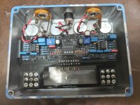
I’ve just finished a Paragon (new version) and have no switch function. There is anywhere from 14-16v sitting on the left switch but only .25v on the right. No bypass signal. LEDs are dim and do not change state when switched. Could this be a switch issue or something else?

Any help would be much appreciated.
 
Your footswitches are installed incorrectly. They're rotated 90 degrees in the board.

Let me see if I have an extra, the chances of removing them without destroying a pad is very slim.
 
Thanks for the quick reply. I’ll attempt removal but I have more switches if necessary.

If I needed to wire the switches in (eliminating the breakout board) would I follow Pedal PCB standards for other switching? Re: the board is not labelled and the jack jumpers are run through the main PCB. If you have a wiring diagram to do this I’ll just eliminate the breakout board altogether.
 
Hi.. I'm facing grounding problems with the Paragon splited board. The same the picture above.
If I connect the enclosure to the ground the right led is on regardless of the position of the right switch. It's always on.
If I disconnect the enclosure to the ground this problem disappears but obviously the hum is tremendous due to the lack of shielding.

Any hint?
Thanks

Jones - Brazil

ps: I've bypassed the charge pump TC1044 because I use a +18V power supply
 

Attachments

  • d38319a9-518f-4b63-9ffa-8d557d4977f6.jpg
    d38319a9-518f-4b63-9ffa-8d557d4977f6.jpg
    217.2 KB · Views: 39
Last edited:
The wiring is slightly different from the usual diagram. I'll post a pinout for you in just a bit.
Gee wizz, so I managed to get the switches out. That was stupid. Flipped ‘em a solid 90 degrees and voila! It worked, sort of. No bypass signal now. No LED either.

Side note: I did originally have the same issue as Jones where, only the right Led was illuminated when grounded.

Welp I’d say this thing sounds fantastic I’d just like it to do what it’s intended to. Any thoughts?
 
you may have damaged your footswitches or the trace connections to the switches on the pcb in the process. use your DMM to test if each of the pins in the middle row of the switches is connecting to the corresponding pins in the outside rows when you activate the switch. you can pay particular attention to the parts that connect to the bypass and the LED, since those aren't working.
 
Back
Top