SOLVED No power after enclosure

KdubATX

Member
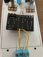
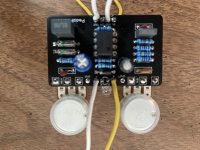
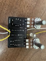
Build powered on when wired to the Auditorium but I’m getting no power after I’ve wired up in the enclosure. Thought I was being pretty careful too :/. Pics attached and I tried to get decent shots of the different spots of interest. Hopefully I just did something absentminded at the end of the build that will be easily fixed tomorrow.
Welcome any thoughts and feedback.

IMG_6480.jpeg
 

Attachments

  • IMG_6482.jpeg
    IMG_6482.jpeg
    389.5 KB · Views: 64
  • IMG_6483.jpeg
    IMG_6483.jpeg
    358 KB · Views: 64
  • IMG_6484.jpeg
    IMG_6484.jpeg
    411.6 KB · Views: 57
  • IMG_6486.jpeg
    IMG_6486.jpeg
    450.7 KB · Views: 58
  • IMG_6487.jpeg
    IMG_6487.jpeg
    417.8 KB · Views: 62
Are you getting no power or just no LED? That bezel is all metal, that will short the LED if you don’t have the small plastic part the legs go in.
 
Looks like you've got a different board version than image in the current listing, so maybe yours is different, but should the two germanium diodes be facing alternate directions like this one?

EDIT: Nevermind. I can see the square pads on the same side on your board. You're good.

1690482017998.png
 
Are you getting no power or just no LED? That bezel is all metal, that will short the LED if you don’t have the small plastic part the legs go in.
No power at all. I’ll try adding some electric tape to the led wire and Jack screws later when I get home to see if it does anything for me.
 
Well stripped the hardware and plugged back in the Auditorium and now have no power there either. Yanked all my connecting wires and replaced with new single strand pieces and after hooking up to Auditorium I got the same result. Signal passes through the bypass channel but the led and effect are not working.
So I did something wrong after starting on the enclosure stage. And whatever it was I have not fixed. New pics attached. May let this one sit awhile then try again later and move into the next one for a bit baring any ideas.
 

Attachments

  • IMG_6505.jpeg
    IMG_6505.jpeg
    379.2 KB · Views: 24
  • IMG_6508.jpeg
    IMG_6508.jpeg
    429.6 KB · Views: 23
  • IMG_6509.jpeg
    IMG_6509.jpeg
    469.1 KB · Views: 21
Ok I’ve binned this project. Too much overworking it probably. Changed the diode but then had no power reading at all and realized I’d managed to snap the negative power wire from all the fiddling with it and things kind of spiraled from there. Pulled the ic and tossed the rest out. Board was starting to look fried and I was getting fried with it. I’ll start fresh with something else and just move on.
 
Starting over on this one and I see the board is oriented a little differently than the build guide. Looking at D1 and D2 (1n270) the positive/negative orientation is reversed on D1.

Would you advise following the orientation as on the board or as on the guide? Pics attached.
IMG_6683.jpeg IMG_6684.jpeg
 
Back
Top