Op Amps and Power

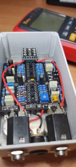
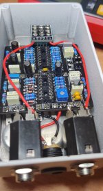
Super noob question. I just finished my second build but like a noob, forgot to order the OP AMPS on the original buy so I had to buy them after and they will come tomorrow. So my pedal is 99% done with slotted IC holders to put the op amps into once they land.

Question. I went to test (with no op amps installed, it needs 4). Would not having the op amps installed cause the pedal not to power on?

It is the Dirty Sanchez. Thank you.
 
The LED should light and you should still have sound in bypass.

Otherwise it won't do anything else.
 
No LED coming on. have in and out cable connected, DC power. no LED comes on. It's fully built sans the 4 op amps I need... Shucks.

Get sound in bypass.
 
Last edited:
20V DC putting red probe in V voltage and black in COM / ground then just stick yer red on + and black on -

20201124_172442.jpg
 
Last edited:
My DMM is "auto sensing" and can pick up whatever I measure. So for POWER, yes I am getting power into the jack itself and also getting power to the PCB in the - and + positions. The reading is 22.5. So yes, power IS coming in.
 
Post a pic so we can see how you've got it set up

I've no idea what voltage it should be looking at the schematic I thought it was 9v I'd assume you've got caps rated for over that

Check what voltage you get cathode of D100
 
Last edited:
Post a pic so we can see how you've got it set up

I've no idea what voltage it should be looking at the schematic I thought it was 9v

Check what voltage you get cathode of D100
Here are two pics.

I switched my DMM to read as DC VOLT.

Reading on my DMM at the black and red lugs of the DC power innie jack is 9.25VOLT

Power at the CATHODE side of D100 when touching ground of DC jack is 9.33VOLT
 

Attachments

  • IMG_20210729_132308.jpg
    IMG_20210729_132308.jpg
    1.1 MB · Views: 9
  • IMG_20210729_132308.jpg
    IMG_20210729_132308.jpg
    1.1 MB · Views: 9
That's ok powers going in check your LED is orientated correctly and you've got voltage on the CLR R107
 
I'm gonna be pretty beefed if I put the LED in backwards. =( I will have to dismantle pretty thoroughly to get to it. I soldered it, shrunk wrapped it, glued it and its' under the board.
I did use a coin cell battery from the back side just to TEST the LED and it glows nice and purple so I know the LED is good.

When you say "CLR R107", i know where R107 is but what is CLR? I need to hold black probe to ground and red probe to either side of R107? I am a noob, I do not know what CLR means. BLESS YOU! EDIT: GOOGLED. CURRENT LIMITING RESISTOR.

EDIT: Getting 9.49VOLT at the R107, either side of it. Red probe at that resistor and black probe on the ground of DC jack.
 
Last edited:
touch the leads of another LED to each contact point on your LED to see if it lights in either arrangement of the two leads. I usually leave the LED unsoldered on a board until everything else is done to make sure I have it oriented correctly.
 
I've had to go back to work but I think you can use your meters diode function to check LED polarity touch the LED legs with red and black probes if it lights briefly with red on anode and black on cathode it's correct if not it's the wrong way round
 
I just totally redid the LED wiring and I put it into a bezel.
Red wire to A for ANODE / POSITIVE and black wire to K for cathode / NEGATIVE.
I can get LED to light up with I touch either side of the board with some small leads and a CR2032 batt (handy trick).

When I power the unit, NO LED comes on.

Getting DC power at hte various places asked, the D100 diode and the CLR R107. 9+V at each. Clearly power coming in and this was a super clean build since I really took my time and did it clean... I will wait for the op amps to come in and maybe when they go in, it will light the LED? darn slow USPS.
 
Last edited:
So you've verified that your LED anode + leg goes to the A pad and cathode - to the K pad

Just to double check you get the same voltage both sides of R107?

One side you should get the same as D100 anode 9v ish the other around 2.5V
 
Last edited:
Yeah coin cell is as good as yer meter diode function to suss orientation if you put the + of the battery on the pin going to A pad and - on pin to K pad and it lit it's correct orientation

So you could be correct with it being the 3PDT connections check your SW and GND pads maybe just reflow them both ends

You can continuity check from SW and GND pads on the main pcb to the 3PDT lugs 4 and 5 top two on the middle row
 
OK! GOT MY OP AMPS. Slotted em, PEDAL IS WORKING. HAVE SOUND FROM PEDAL WITH OP AMPS NOW.

However, still no LED. WIll try this next:

So you could be correct with it being the 3PDT connections check your SW and GND pads maybe just reflow them both ends

You can continuity check from SW and GND pads on the main pcb to the 3PDT lugs 4 and 5 top two on the middle row
 
20210730_002537_copy_432x510.jpg
Make sure they connect as shown and middle lug 5 connects to ground and those 2 lugs 4 and 5 have continuity in effects mode

SW should also have continuity with LED K pad

What happens is switched to effects mode middle and top rows connect you're connecting your signal from in jack to circuit in through the circuit to circuit out and out jack at the same time connecting lugs 5 ground to lug 4 grounding your LED cathode and lighting it to indicate it's in effects mode

So once you continuity check it you'll know if it's all connected as it should be now that you've checked everything else it must be a poor connection to ground
 
Last edited:
Back
Top