You are using an out of date browser. It may not display this or other websites correctly.
You should upgrade or use an alternative browser.
You should upgrade or use an alternative browser.
SOLVED Paragon Mini: One LED, no sound, no bypass when plugged in
- Thread starter apierz
- Start date
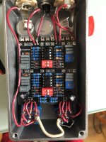
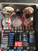
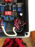
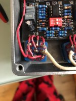
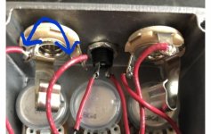
Looks like you reverse your cable on the input/output jack. Sleeve should be ground and tip should go to your switches.As it says in the title, when I connect my pedal to power I can turn on the right LED but I don't get any sound, bypass or otherwise. The left LED won't turn on at all. This is my first pedal build so any advice on what might be wrong or how to troubleshoot would be appreciated.
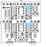
View attachment 23307
View attachment 23308
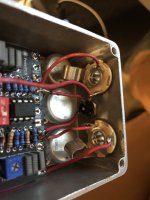
View attachment 23309
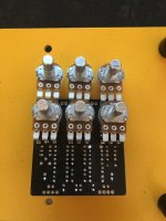
View attachment 23310
Yes pretty sure they are... I use the exact same...Are they both wrong? I have had a very hard time trying to look up which lead is supposed to go to which part of the pcb.
This will help:
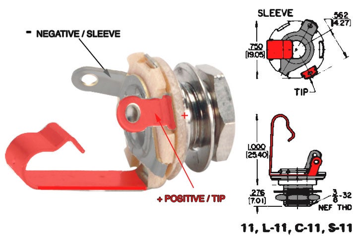
I'm trying to imagine how this can be possible considering you had them definitely reversed... I just can't wrap my head around this..View attachment 23332I tried swapping the wires but still no sound and now I don't get a signal through the pedal when it is not plugged in like I was getting before.
I checked you switch wiring and all seems good, other than with the pic I can't confirm you don't have any solder bridge, So I would start with that. Make sure you solder all lugs cleanly, have the plastic shielding as close to the lug as possible and nip to extra strands clean.
Other puzzle is why wouldn't the other led to turn on, it's the same power supply... Can you check if you have voltage at the left pad of the led when you engage the footswitch ? You may have reversed the LED.
Thank you everyone for your help. It means a lot to know that you're not banging your head against the wall by yourself! I ended up taking out the parts and replacing components to see if I could find the issue and it looks like the culprit was a bad footswitch (I probably cooked it while soldering it in). It seems to be working fine now. Thanks again!
droneshotfpv
Active member
Footswitches, if / when heated TOO much will absolutely melt inside (ask me how I know). That's why it's good to have a hot iron. What iron do you have, and what is your temp setting? I use a Digital Solder Station, as well as a T12 solder station, and crank my iron to around 370 - 380 degrees Celsius. I say Celsius because A.) I am too lazy to convert B.) Because China C.) Back to Lazy... too lazy to switch to FahrenheitThank you everyone for your help. It means a lot to know that you're not banging your head against the wall by yourself! I ended up taking out the parts and replacing components to see if I could find the issue and it looks like the culprit was a bad footswitch (I probably cooked it while soldering it in). It seems to be working fine now. Thanks again!
You want to have the iron on there for no more than a few seconds at best.
Glad you got it figured out, and it wasn't a complete de-solder and rework of the board, because for me, that is when stuff starts miraculously catching fire that makes me angry.... lol
Footswitches, if / when heated TOO much will absolutely melt inside (ask me how I know). That's why it's good to have a hot iron. What iron do you have, and what is your temp setting? I use a Digital Solder Station, as well as a T12 solder station, and crank my iron to around 370 - 380 degrees Celsius. I say Celsius because A.) I am too lazy to convert B.) Because China C.) Back to Lazy... too lazy to switch to Fahrenheit
You want to have the iron on there for no more than a few seconds at best.
Glad you got it figured out, and it wasn't a complete de-solder and rework of the board, because for me, that is when stuff starts miraculously catching fire that makes me angry.... lol
Yes like @droneshotfpv said... also you should consider buying the 3PDT break out board. They will make your life so much easier.Thank you everyone for your help. It means a lot to know that you're not banging your head against the wall by yourself! I ended up taking out the parts and replacing components to see if I could find the issue and it looks like the culprit was a bad footswitch (I probably cooked it while soldering it in). It seems to be working fine now. Thanks again!
When soldering a switch, it's also good to use a star pattern that let the previous lug cool off. I try to never solder consecutively any horizontal or vertical lugs
Sort of a pattern like this:

There's probably even better patterns... you can find your own...

