Paragon, No Sound

MoanaNui

New member
Hello all,

Thank you in advance for taking the time to have a look at my problem.
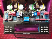
Bypass works, no sound when either footswitch is engaged, LEDs do light up. I checked for any shorts, reflowed all (I think) connections, checked for continuity between footswitch board and main board (all good), and checked to make sure the footswitches had continuity in active and bypass modes (all good). It appears that it may be something to do with the power coming in?

Power in voltages:
D7: 9.8v
Pins 1& 8 on IC3 (no IC inserted): 3.7v
D14: 3.7v
D15: 1.8v
C21: anode 1.8v, cathode 1.2v
C22: anode 1.2v, cathode 1.v
C11: 0v

With all of the IC's in place, I get 9.8v at the anode of D7, and 0v at the cathode and pins 1/8 on IC3.

Thanks again for taking the time!
 

Attachments

  • IMG_3633.jpg
    IMG_3633.jpg
    852.1 KB · Views: 25
  • IMG_3630.jpg
    IMG_3630.jpg
    582.4 KB · Views: 24
  • IMG_3631.jpg
    IMG_3631.jpg
    520.3 KB · Views: 23
  • IMG_3632.jpg
    IMG_3632.jpg
    738.6 KB · Views: 23
D7 cathode should be around 9.4v power in, less it's forward voltage drop so your problem is there

If there's 0v at D7 cathode you'll have no power going to the circuit the LEDs are powered prior to D7 so would light up

You can for test purposes just jumper D7 if reflowing the joints doesn't solve it
Thanks for the response. I swapped out D7 (for the second time) and now am getting the correct voltage at the cathode, the next two down the line still have a huge drop at their cathodes, down to 3.4v after D14. All those measurements are with IC3 out. When it's in, I get 0v at the D7 cathode.
I've ordered some more 1N5817's from a different seller and will swap those out when they get here. Hopefully that does the trick and I don't destroy the pcb too much while popping them out.

Thank you again
 
It sounds like your ground and power are shorted. With the power off measure for continuity/resistance between D7 cathode and ground. If they are shorted then you will need to work out where - could be a poor solder joint, a pot without proper insulation on the back, a dead component. Actually, if putting IC3 in creates the problem then probably IC3 is the problem
 
What are the voltages on all IC3 pins, in and out of socket

Where did you get your IC
IC3 voltages:
IC Out
1: 9.75
2: 2.9
3: 0
4: 2.8
5: 0
6: 0
7: 0
8: 9.75

IC installed, 0v on all pins. I got the IC from Tayda, I just ordered some new ones from Stomp Box Parts. Hopefully it was just a bad/damaged IC.
 
Your out of socket voltages are what you'd expect ie power getting to pins 1 and 8 a little charge on 2 and 4 from the caps and 0 on pin 3 and the unconnected pins 5, 6, 7

So a good possibly the ICs a goner

Whilst you wait for yer new ICs

I'd do a visual inspection under magnification around IC3 and it's components just to make sure there's no solder bridges etc making it act funky when it's in socket

Check the only pins with continuity on the socket are 1 and 8 just to make sure you've no bridges on the socket you can't see

I had an IC with good voltages out of socket and way out in socket so thought it was the IC swapped it out and it was still the same

Eventually I found a solder bridge which was only connected when the IC was active in the socket which gave me the whacky voltages by shorting to a resistor when the active component (the IC) was active so to speak

So worth a check
 
While taking the time to poke and look around in there as suggested, I noticed that I had continuity between pins 1/8 and pin 7, and only when the IC was installed. When checking the non-installed IC3 there is continuity from pins 1-8, 8-7, and no beep from 1-7. There is no beep from 7 to 1 or 8 on the socket connected to the board. I took a good look around and didn't see much, but replaced the IC socket just in case there was something hiding underneath that I could see. The problem is still there. So now I wait for the new IC's to show and hope that does the trick.
 
Hello, I have been following this thread because, I too, have one channel that doesn't work. It initially worked, but stopped. I've taken out of the enclosure and have gone through everything in this thread plus additional stuff. I have replaced all IC's.. BUT, the one proble I have on mine, on the channel that is faulty, The ic has 16.75 Volt on pin 1??? I am certain this is not right, but does anybody know what would cause this??? I am not sure where to look. The probe has been hit or miss, however, I believe my issue is this voltage?? IC out of socket, voltages appear normal. I have put 4 different IC's in there, all new and pin 1 reads 16.75 V?
 
Back
Top