

You are using an out of date browser. It may not display this or other websites correctly.
You should upgrade or use an alternative browser.
You should upgrade or use an alternative browser.
SOLVED Point to point issue
- Thread starter Discobungle
- Start date
chris.knudson
Well-known member
It's really impossible to tell based on the information we have. A schematic would be helpful and knowing the pin-outs of the transistors would ne be necessary to trace the circuit. Having said that, did you test the circuit before you wired the foot switch? I've never seen a foot switch wired like this, and if I had to pick a starting point, it sounds like you are sending your signal to ground when you engage the pedal.
Bricksnbeatles
Member known well
The easiest place to start is checking for shorts— Set your multimeter for continuity and probe around all the different points in the circuit while one lead is clipped to the enclosure. If you get a beep, and it’s not a part that should be connected to ground, then it’s probably shorting against the enclosure.
A schematic and the transistors you used would be helpful to diagnose anything beyond a short tho
A schematic and the transistors you used would be helpful to diagnose anything beyond a short tho
chris.knudson
Well-known member
Assuming that leg 1 of the pot is ground, then I think it's correct, but again a schematic would be helpful.Is the Electrolytic facing the wrong way on the Left side coming of leg 1 of the Top Left B50K Pot?
Is the Electrolytic facing the wrong way on Leg 1 of the Top Left B50K Pot?Morning. I breadboarded and then built this point to point pedal. I’m only getting bypass at this point. Any ideas?
Thanks in advance!
Last edited:
The Pot is coming off the Input from the footswitch I think???, this is more fun than a PCB!Assuming that leg 1 of the pot is ground, then I think it's correct, but again a schematic would be helpful.
chris.knudson
Well-known member
Exactly why I asked about the foot switch wiring. I can't tell, but I think that when you engage the foot switch, you're dumping the signal to ground???The Pot is coming off the Input from the footswitch I think???, this is more fun than a PCB!
Discobungle
Member
All good points. I’ll be home in a few hours and will upload schematic. Thanks for the discussion.
chris.knudson
Well-known member
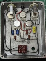
Ok, I think I'm starting to understand the foot switch. From what I can tell, the center lug of the right side of the foots switch goes to the tip of the output jack. the center lug in the middle of the switch goes to the tip of the input jack, so when the switch is thrown to the top half, the jumper between the top right and top center lugs create the bypass (which we know works).
The bottom right lug goes to pin 2 on the A100K (presumably a volume control), and the bottom center lug goes to pin 2 on the B50K (presumably a drive pot). That all makes sense to me now. What was throwing me was the ground connection to the center pin on the left side which doesn't connect to anything, but I guess that's for the connection to the LED and CLR, which would then connect to the positive rail.
Assuming all of that is correct, the next thing I'd look at is the pin out configuration on the transistors.
chris.knudson
Well-known member
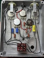
Yeah, that's my guess. It looks like a silicone fuzz with a tone stack.I believe the Top Right Pot under the Output jack is Volume, Leg 1 is going to Ground, Leg 2 is going to Output on the bottom right of Footswitch, Leg 3 is going to 10nf Yellow Cap to Leg 3 of the 1K Gain pot ??? so we are talking Fuzz circuit???
Discobungle
Member
Discobungle
Member
Yes. My take on the Fulltone 69 with an added bias control.I believe the Top Right Pot under the Output jack is Volume, Leg 1 is going to Ground, Leg 2 is going to Output on the bottom right of Footswitch, Leg 3 is going to 10nf Yellow Cap to Leg 3 of the 1K Gain pot ??? so we are talking Fuzz circuit???
Discobungle
Member
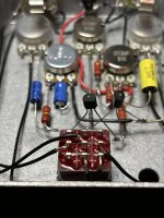
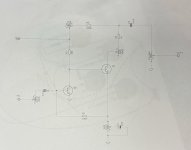
I also noticed that my Q2 was in backwards. Fixed that but still no effect signal.I really appreciate you guys taking your time to help me out with this. Attached you will find the schematic and the transistors that I used are NOS Fairchild, 2N2926 NPN silicon. Thanks again.
chris.knudson
Well-known member
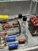
Based on the data sheet I'm looking at, it looks like Q1 is in backwards.
EDIT: With the flat side facing toward you the pins from left to right should be ECB.
EDIT: With the flat side facing toward you the pins from left to right should be ECB.
Last edited:
Discobungle
Member
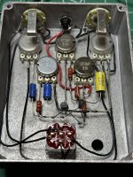
I checked and I think it’s correct. E of Q1 goes to ground. B goes to C2 and 100k and C goes to B or Q2 and 33k. Here’s a more clear pic. I did switch Q2 around earlier though.Based on the data sheet I'm looking at, it looks like Q1 is in backwards.
EDIT: With the flat side facing toward you the pins from left to right should be ECB.
Attachments
chris.knudson
Well-known member
Yeah, that should be correct.I checked and I think it’s correct. E of Q1 goes to ground. B goes to C2 and 100k and C goes to B or Q2 and 33k. Here’s a more clear pic. I did switch Q2 around earlier though.
Discobungle
Member
chris.knudson
Well-known member
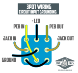
Yeah, that means your input is shorting to ground. And I'm all kinds of confused about the way you have the foot switched wired now. I had just wrapped my mind around how you had it wired before. I'm going to have to study this for a minute...I’m also getting continuity between pin 2 of the 50kb and ground. No idea where that’s coming from. Changed the 3PDT wiring a bit too. Here’s a pic.
chris.knudson
Well-known member
Ok, I think you just flipped the wiring from the way you had it wired before. I'm struggling to follow what is happening on the right side of the switch. I know there are a dozen ways to wire a bypass switch, but the easiest one for me to wrap my mind around is this one...
Attachments
Last edited:
Similar threads
- Replies
- 1
- Views
- 156
- Replies
- 21
- Views
- 716