jinx_defusing
New member
Hi there,
Two questions from a total noobie:
I hate outboard wiring. It is the bane of my existence. So I purchased those power I/O modules, because it looks like it would make things a lot more simple. I also recently ordered the pineapple distortion (wampler pinnacle clone). Now, this motherfucker requires 6 j201s. 6 of them. So I ordered 10 on mouser (holy shit these SMD things are microscopic), and also ordered the SMD adapters from PPCB.
So here's my problem- the power I/O modules and the SMD adapters don't come with any sort of build docs or instructions. I am guessing there's no information about them because they must be so easy and intuitive to use, but I still don't know what the hell I am supposed to do with them.
Question #1: Power I/O Module-
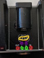
The ones that arrived do not look like the ones in the picture on the website. The ones that arrived have twice as many through holes. They are labeled, but it is not clear which holes the labels correspond to. Let me show you what I mean by that:

The red circles: I am assuming these are for the long wires that would connect the tips (live) of the mono jacks to the 3pdt switch?
Green and purple: ok... so this is confusing. There is a positive and negative symbol. Which holes do those symbols correspond to? All 4 holes? Just 2 of those holes? Which ones? I am guessing that these symbols are just for the purple holes...
The purple hole on the right side has a trace leading to the dc jack... so this is the way that power is supplied to the pcb. Right? And I'm guessing the one on the left is the ground connection. So the purple holes correspond with the positive and negative symbol and would normally connect to the tip (+) and sleeve (-) of the dc jack?
Then does that mean that the green holes are for the wire that would normally be used for the sleeves of the mono jacks (ground)?
Yellow holes: i can ignore these, right?
Question 2: j201 adapters
what in the actual fuck do i do with these? I know i am supposed to solder the SMD to these little fucking boards. But how do I connect them with the main pcb? Do I buy some of those pins that one might typically use for breadboarding? Also... specifically for the pineapple distortion... how are all of these little adapters going to fit? are they supposed to be soldered to the pins that I attach to the main board? And do they just sort of float above all the other components? I don't see how else these would fit...
Two questions from a total noobie:
I hate outboard wiring. It is the bane of my existence. So I purchased those power I/O modules, because it looks like it would make things a lot more simple. I also recently ordered the pineapple distortion (wampler pinnacle clone). Now, this motherfucker requires 6 j201s. 6 of them. So I ordered 10 on mouser (holy shit these SMD things are microscopic), and also ordered the SMD adapters from PPCB.
So here's my problem- the power I/O modules and the SMD adapters don't come with any sort of build docs or instructions. I am guessing there's no information about them because they must be so easy and intuitive to use, but I still don't know what the hell I am supposed to do with them.
Question #1: Power I/O Module-
The ones that arrived do not look like the ones in the picture on the website. The ones that arrived have twice as many through holes. They are labeled, but it is not clear which holes the labels correspond to. Let me show you what I mean by that:

The red circles: I am assuming these are for the long wires that would connect the tips (live) of the mono jacks to the 3pdt switch?
Green and purple: ok... so this is confusing. There is a positive and negative symbol. Which holes do those symbols correspond to? All 4 holes? Just 2 of those holes? Which ones? I am guessing that these symbols are just for the purple holes...
The purple hole on the right side has a trace leading to the dc jack... so this is the way that power is supplied to the pcb. Right? And I'm guessing the one on the left is the ground connection. So the purple holes correspond with the positive and negative symbol and would normally connect to the tip (+) and sleeve (-) of the dc jack?
Then does that mean that the green holes are for the wire that would normally be used for the sleeves of the mono jacks (ground)?
Yellow holes: i can ignore these, right?
Question 2: j201 adapters
what in the actual fuck do i do with these? I know i am supposed to solder the SMD to these little fucking boards. But how do I connect them with the main pcb? Do I buy some of those pins that one might typically use for breadboarding? Also... specifically for the pineapple distortion... how are all of these little adapters going to fit? are they supposed to be soldered to the pins that I attach to the main board? And do they just sort of float above all the other components? I don't see how else these would fit...

