SOLVED Pro10 Green Tone Sucking in Bypass?

youngkong10

New member
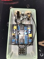
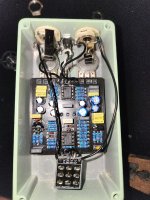
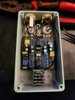
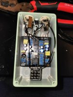
I'm having an issue with the Pro-10 Green Overdrive I just built, the pedal seems to work fine when on, but has serious treble/volume loss in bypass. I already tried reflowing the jacks and changing the 3pdt for a fresh one with a new board. Same issue though. I checked all the resistors with a multimeter and they read fine as well. I don't understand what could be affecting the bypass since it just goes from one jack through the bottom of the switch and out the other jack? Please let me know if you have any ideas. I'll post a picture of the build but note that the 3pdt in/gnd/sw/out wires are disconnected because I was in the middle of resoldering the switch.
 

Attachments

  • 20231211_182947.jpg
    20231211_182947.jpg
    249.5 KB · Views: 27
  • 20231211_183004.jpg
    20231211_183004.jpg
    237.4 KB · Views: 26
Solution
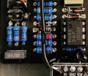
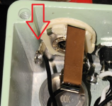
This wire is possibly compromised, and the connection of this wire to the tip lug of the input jack looks questionable. Replace this entire wire, and be sure you get the lug on the jack hot enough for solder to flow.

20231211_215117.jpg
I have to see the finished 3pdt in order to help you. The pedal looks fine except for the footswitch wiring. Once you have that finalized, please post the photo, and I'll take look to see if I can help you.
 
I have to see the finished 3pdt in order to help you. The pedal looks fine except for the footswitch wiring. Once you have that finalized, please post the photo, and I'll take look to see if I can help you.
The 3pdt is not the issue, I not only swapped it for a new switch but I also used my DMM to check continuity for each wire, and to check that there was no continuity between them. Do you have any ideas of what it could be outside the switch wiring?
 
The 3pdt is not the issue, I not only swapped it for a new switch but I also used my DMM to check continuity for each wire, and to check that there was no continuity between them. Do you have any ideas of what it could be outside the switch wiring?
I'm with @chris.knudson on this, if you think this is the best you can do with the footswitch to PCB connections, we can't help you.
To be Honest, If it is working via those connections , it's a miracle!
also, you may want to check that your in & out jacks are not touching the post in the corners of the enclosure???
If this is what you have now shown above, it's a mess:

What is This ,jpeg.jpg
 
I'm with @chris.knudson on this, if you think this is the best you can do with the footswitch to PCB connections, we can't help you.
To be Honest, If it is working via those connections , it's a miracle!
also, you may want to check that your in & out jacks are not touching the post in the corners of the enclosure???
If this is what you have now shown above, it's a mess:

View attachment 62964
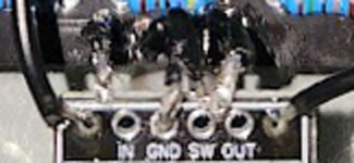
No no you misunderstand, the connections are soldered properly I just took the photo in the middle of swapping the switch out. I tried to say that in my original post. I used different wires, a different breakout board, and a different switch as well as checking continuity to make sure that wasn't the problem. I did check the jacks terminals and they are clear, I even tried the pedal outside the enclosure entirely and it was the same. Do you have any idea what I could be outside of the switch?
 
Honestly, I don't know what the issue might be. I can't tell what's going on with the J201, but I do need to see your final footscwithch connections before I can give you anything productive. As @music6000 says, I'm surprised it works at all with the way the footswitch is wired. I'm definitely here to help, but I just don't have enough information to help you with this yet.
 
Honestly, I don't know what the issue might be. I can't tell what's going on with the J201, but I do need to see your final footscwithch connections before I can give you anything productive. As @music6000 says, I'm surprised it works at all with the way the footswitch is wired. I'm definitely here to help, but I just don't have enough information to help you with this yet.
No... you guys. You've got it wrong. The footswitch never worked like this, this was a photo taken mid switch change. I said in the original post "note that the 3pdt in/gnd/sw/out wires are disconnected because I was in the middle of resoldering the switch.". The j201 is the smd one from pedalpcb, but I ran out of through hole adapters so I used some wire to connect the terminals in the same way they are shown for the adapter that pedalpcb sells. I'll take another photo in a few minutes, and btw I really do appreciate that you are here and helping because I'm really lost on this one.
 
  • Like
Reactions: Nic
No... you guys. You've got it wrong. The footswitch never worked like this, this was a photo taken mid switch change. I said in the original post "note that the 3pdt in/gnd/sw/out wires are disconnected because I was in the middle of resoldering the switch.". The j201 is the smd one from pedalpcb, but I ran out of through hole adapters so I used some wire to connect the terminals in the same way they are shown for the adapter that pedalpcb sells. I'll take another photo in a few minutes, and btw I really do appreciate that you are here and helping because I'm really lost on this one.
I understand that the footswitch isn't the issue. I just need to see it finished so that I can trace the circuit. I really do want to help you figure this out.
 
I understand that the footswitch isn't the issue. I just need to see it finished so that I can trace the circuit. I really do want to help you figure this out.
Here are the finished pictures, same issue... I tried swapping out the j201 as well to no avail.
 

Attachments

  • 20231211_215117.jpg
    20231211_215117.jpg
    379.9 KB · Views: 21
  • 20231211_215104.jpg
    20231211_215104.jpg
    484.2 KB · Views: 21
Could be due to the "tip" parts of your jacks touching the enclosure. Unscrew them, take them out of the enclosure and test again.
That's a good thing to check, you could try rotating them but taking them out of the enclosure is a foolproof way to check.

Just to reiterate what Chris was saying, the pedal is wired as true bypass, so when it's bypassed the signal goes Input Jack -> 3PDT -> output jack. It shouldn't enter the PCB at all. So the J201 is irrelevant, for example.

I would check jesuscrisp's suggestion first, also clean out at least one of the in/out jack holes in the enclosure so the jack makes contact to the bare aluminum (so it's grounded on the chassis), and then triple check the 3PDT daughterboard. FWIW I've also had bad experiences with daughterboards like that and usually just wire the switch directly like shown in the build document. Desoldering the daughterboard is probably not going to work well tbh (you can try, but getting the 3PDT out is a pain), so if it comes to that I would just get another new switch and try with that.

Edit: Might be worthwhile to check your cables too if you can't find other issues, since it could be one of the cables you use to connect the Pro 10 and you just don't notice the same tone suck while the pedal is turned on.
 
Last edited:
Thanks for all the suggestions guys, the cap in the corner is a 560pf MLCC. I have already tried the pedal entirely out of the enclosure but it sounds the same. I am testing the pedal by itself. I'll try cutting some new wires for the jacks and see if that helps next, and I'll let you know here.
 
Like others have mentioned, there are only four things that can affect bypass...

Wiring, jacks, footswitch, or something outside of the pedal (patch cables).

You can ignore the DC jack and everything on the Pro-10 PCB, none of that will affect your bypassed signal.


I know you said it was the same out of the enclosure, but regardless, this jack needs to be rotated so that lug isn't touching the enclosure.
1702395323822.png
 
Last edited:
Thanks for all the suggestions guys, the cap in the corner is a 560pf MLCC. I have already tried the pedal entirely out of the enclosure but it sounds the same. I am testing the pedal by itself. I'll try cutting some new wires for the jacks and see if that helps next, and I'll let you know here.
That was it! There was a burn mark on the input cable and it must have restricted the signal too much or something, sounds great now thank you everyone!!
 
Back
Top