Question about blend pot VS switch

radam84

Member
So I plan on building a RAT and have a turbo RAT layout I was going to follow. I decided that I was going to use a switch for different clipping options, but then thought about a pot and if that would work. So would a pot work for blending in-between differnt diode pairs? If someone tells me that it would work Im sure I can figure out how to wire it up myself, I guess Im also curious if it would a good idea or bad idea as in functionally as well. What I'm hoping I guess is that at zero Id have just LED clipping and then at full CW I have something else(not sure what diodes Id use yet) and then everything in-between would be something A-symmetrical. Do I have that right? I havent actually built anything yet so still researching and learning whats possible.
 
That's an interesting idea. I'm not sure how useful it would be but who knows?

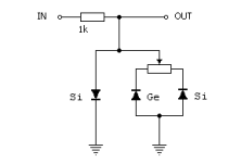
If it was in a typical Rat then the clipping diodes go to ground. So I would guess that you would wired pin 2 of a pot to ground, pin 1 to the end of one set of clippers and pin 3 to the end of another set of clippers. The other end of the clipping diodes would connect to where clipping diodes connect in a Rat. I have no idea what value pot to use. I'd start with B100K I guess. The pot value would have to allow one set of diodes to dominate but still let the other set gradually fade in, so maybe a 100K might work too much like a switch? I dunno!
 
Jack Orman describes exactly this on his website: https://www.muzique.com/lab/warp.htm

warp9.gif
 
I was thinking about this again last night, didnt really research it or anything when I guess I should just do that, but Im going to ask here anyways. Will the resistance of the pot affect the clipping and if so, how? If the Jack Orman link from above explains this, disregard this question. Im gonna go check that link out right now. Cheers.
 
That's an interesting idea. I'm not sure how useful it would be but who knows?

If it was in a typical Rat then the clipping diodes go to ground. So I would guess that you would wired pin 2 of a pot to ground, pin 1 to the end of one set of clippers and pin 3 to the end of another set of clippers. The other end of the clipping diodes would connect to where clipping diodes connect in a Rat. I have no idea what value pot to use. I'd start with B100K I guess. The pot value would have to allow one set of diodes to dominate but still let the other set gradually fade in, so maybe a 100K might work too much like a switch? I dunno!
somehow I missed your post last time I checked this, my bad. Thank you for your explantion eh. Yea I started wondering about how resistance would effect things. I know what the components in a circuit are and know what most of them do, but as to how they all work together is where I get a bit lost lol. Guess Ill just have to give it a go and see what happens, in my head it seamed to make sense and seemed to be an interesting way of doing things. The link Robert shared Im sure will give me more insight into the idea, still have to read that. Unfortunately after my message saying I was going to read it right away, I got distracted.
 
Ha! In the Jack Orman he does exactly what I suggested except the other way around. I guess the odds are 50/50.
 
Ha! In the Jack Orman he does exactly what I suggested except the other way around. I guess the odds are 50/50.
Yea that was a good read. The picture Robert shared is what was in my head as the idea but after reading that page I kinda like the idea of this: 1709293910074.png
 
I did exactly this on a rat build awhile back. One side of the pot is led and the other side is asym silicon. Works great. I love the added flavor I can dial in.
 
Back
Top