Questions for Cataclysm Tap Tempo Mod

debrad

Active member
I recently bought a Tap Tempo board from another site in hopes of adding this functionality to my Cataclysm (Disaster Transport Jr.) build. I’ve been going through some of the documentation today and think I have a handle on just about everything except the difference between the Cataclysms B50k "Time" potentiometer and the replacement B100k pot on the tap tempo board.

In stock form, what difference does 50k vs. 100k make on the time function given the PT2399 portion of the Cataclysm schematic (below)? Will there be a significant change to the circuit if I just use the 100k pot instead of the stock 50k?
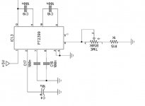
CataclysmPT2399 Schematic.JPG

If you think I should stick with the Cataclysm's 50k pot, I read that the Tap Tempo controller chip (TapTation kit) can simulate the 50k value by connecting the board's Tempo Double Time input to ground. On the tap tempo board, Pin11 of the IC goes to a SPST “double time switch” (S4 on the TapTempoBoard Schematic below) which is either open or connected to ground. Would that be my “Tempo Double Time input” or is that the “output”? Since it switches between open and ground, am I safe in assuming that is NOT the output and that connecting it to ground before the switch that switches it to ground wouldn’t help with the 100k vs 50k pot issue? Would I take something else to ground to take care of this?
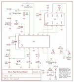
TapTempoBoard Schematic.JPG


My final question: the delay circuit that the Tap Tempo board was developed for shows a 1K resistor coming off PIN6 of the PT2399 BEFORE the 100k Time control (R9 on the DLay Schematic below) while the Cataclysm circuit shows a 1k resistor (R15) AFTER the 50k Time control (the tap tempo board taps off the R9 resistor replacing the B50k Time pot AND the parallel 150k resistor (R22)). Should I make sure there is still a 1k resistor in series with the Time control given the fact that the TapTempo board has ANOTHER 1k resistor (R6) in series with its Time control (i.e. the DLay circuit has 2k in series with the Time pot after the mod...should the Cataclysm have 2k also or just the 1k on the tap tempo board)?
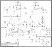
DLay Schematic.JPG

Thanks so much. I look forward to your replies.


- brad -
 
The pot/resistance value determines how long between repeats. The 2399 gets distorted after about 350ms so most guys keep it under that to avoid distortion. Bigger pot means more delay time but more risk of introducing distorted repeats (every chip is different). I stick a 500k pot in there because I don't want pristine, or as pristine as a 2399 will go (not very).

The 1k is an antilatch resistor and sets the minimum delay time. Lower that at your peril as it can cause the unit to freeze up which means removing the power and resetting the thing.

You should always socket 2399s. Some are shite, some are decent, it's the silicon lottery in pedal form.
 
Thanks @BurntFingers. The "specs" on the Cataclysm say it does approx. 625ms with the stock 50k pot, does that sound right? Regardless, it sounds like I should be just fine going with the tap tempo board's 100k pot (I'm not all that concerned with "pristine"). As for the 1k "antilatch resistor", if I'm reading your message correctly, I'll make sure that when I bypass the Cataclysm's Time pot, that I still have a 1k in series with the 1k on the tap tempo board.
 
Thanks @BurntFingers. The "specs" on the Cataclysm say it does approx. 625ms with the stock 50k pot, does that sound right? Regardless, it sounds like I should be just fine going with the tap tempo board's 100k pot (I'm not all that concerned with "pristine"). As for the 1k "antilatch resistor", if I'm reading your message correctly, I'll make sure that when I bypass the Cataclysm's Time pot, that I still have a 1k in series with the 1k on the tap tempo board.
625ms on a 2399 is possible, and the Taptation will actually let it run longer. It’ll just sound lo fi as it gets longer. I personally like that sound.
 
The 1k is an antilatch resistor and sets the minimum delay time. Lower that at your peril as it can cause the unit to freeze up which means removing the power and resetting the thing.

I was doing a little more reading on the Tap Tempo board I've purchased (The Tone God's "TapTation") and, when he first introduced it in the forums of diystompboxes.com, he and several others mentioned using it with the Deep Blue Delay and the Rebote Delay. In those discussions he specifically said to remove the 2.7k resistor on PIN6 of the DBD's PT2399 and the 1k resistor on PIN6 of the Rebote's 2399.

Having read that, I just want to make sure I don't wind up with too little or too much "antilatch" resistance given the fact that the STOCK Cataclysm has a 1k in series with PIN6 and its Time pot and the TapTation board has its own 1k resistor in series with the new Time pot it uses to replace the Cataclysm's.

Easy enough for me to try it both ways but, for the sake of doing it right the first time, do I keep the stock Cataclysm 1k giving me 2k total in series with the TapTation Time pot or do I bypass the Cataclysm's 1k leaving me with a single 1k on the TapTation board in series with the Time pot?

Apologies in advance if I appear to be missing the obvious...I really appreciate your help and clarification.
 
If you socket that resistor you could try different values or even drop a jumper in there if you decide to bypass. Probably your best bet and easy to test.
 
I was actually looking into doing this mod. Curious how yours turned out. Got any pictures of how it ended up?
 
I've had a few other projects come up that have taken priority over my modified delay so I haven't done this yet. Now that my daughters kindly bought me a couple of breadboards for Christmas, I should be able to test the two options quite easily as recommended by @Danbieranowski above.
 
Hi folks!

Following up on this one now that I finally finished building the circuit and boxing it up. I'm really happy with the way it all turned out...delay sounds great and the TapTation board does everything it promises. I used the 1K resistor on the Cataclysm board (R15) and the 100k pot specified in the TapTation documentation.

I do have one minor issue and it seems to be relatively common for these kinds of circuits: I get a noticeable "tick" whether the delay is on or off that is perfectly in sync with the setting of the TempoScale/DoubleTime switches. Interestingly, the tick disappears under all of these circumstances:
  • The delay follows a buffer (i.e. Boss pedal (on or off) or dedicated buffer)
  • The delay follows a true bypass pedal that is turned on
  • The delay is in the effects loop of my amp
  • The guitar volume is set to zero
  • The input jack is jumpered to ground
  • The board input is jumpered to ground
If I remember correctly, the tick was not there when I was testing the build before boxing (I may be wrong) and the only thing that really changed was adding the LEDs to the TapTation board. I should point out that I modified the LED wiring using bi-colour "common anode" LEDs so their positive legs are getting power from the TapTation board, one cathode goes to either side of the 3PDT bypass switch, and the centre lug of the 3PDT is wired to the GRND solder pad between the input and output pads.

I've tried moving the input wire and that doesn't seem to change anything. I was thinking of wiring the LED ground from the 3PDT direct to the DC jack (separating analog and digital grounds?) and I've read a few pointers on adding caps to IC pins or replacing TL072 chips with LM358, TL022, and TL062 alternatives but haven't gotten that far yet. If anyone has any recommendations, I'd love to hear them.

In the meantime, I'm REALLY curious to know if anyone can explain why the tick goes away in the 6 scenarios above? They all seem like pretty common fixes but I'd love to really understand how and why they fix the tick!
 
Well...I tried a few different things (including the addition of shielded wire) but it seemed like grounding the LEDs directly on the DC jack rather than on the circuit board got rid of the tick. I happily put everything back together, closed up the enclosure, plugged everything in and the faint "tick, tick, tick..." was back. I moved a few wires around and it got much quieter but it's still there if I crank the amp volume loud enough (and still gone under the scenarios listed in my original post). On top of that, I seem to get additional hum in the TapTation's "dotted 8th" position and some motoboating at delay time settings greater than noon.
 
Well...I tried a few different things (including the addition of shielded wire) but it seemed like grounding the LEDs directly on the DC jack rather than on the circuit board got rid of the tick. I happily put everything back together, closed up the enclosure, plugged everything in and the faint "tick, tick, tick..." was back. I moved a few wires around and it got much quieter but it's still there if I crank the amp volume loud enough (and still gone under the scenarios listed in my original post). On top of that, I seem to get additional hum in the TapTation's "dotted 8th" position and some motoboating at delay time settings greater than noon.
Is the tick still there on battery power? I had ticking with mine when I was using a cheap power supply. Once I got a quality isolated power supply the problem went away.

Robert
 
Well...I went down to see if I could test your question with a battery attached to my daisy chain cables (Power-All provided at snap adaptor) and it wound up blowing the L78L05 on the TapTation board (TWICE!). Sad that it took two strikes for me to realize that a battery attached to that adaptor is literally "polar opposite" than a pedal snap attached to the adaptor! Fortunately, it appears the L78L05 on the Cataclysm board is OK, I just need to find a 3rd L78L05 for the TapTation...or find a 5v tap on the Cataclysm board to connect to the TapTation.

So, all of that to say, "no" I haven't been able to test the build with anything other than my Power-All and OneSpot daisy chains...

Eek, sorry about that 😥 I have a 9v -> 2.1mm adapter that I reversed the wiring on that I test everything with before boxing just to make sure there's no funny noises. When I first started building pedals (which wasn't all that long ago) the first few always had some funny noises and I wasn't sure what the hell it was and I spent tons of time trying to debug it only to figure out that it was the cheap 9v adapters I was using. I specifically remember the Cataclysm ticking but it wouldn't happen all the time. It depending upon where I had it hooked up in the chain/effects loop. Good Luck

Robert
 
Don't worry, it's all on me (ha ha ha). I just ran through a similar fight with a custom build...the thing was broadcasting AM radio like gangbusters in my test rig. I finally gave up and completely boxed it up...dead silent after that!

I should have probably just been happy knowing the ticking went away when I put the delay after a buffer or in my amp's fx loop but my OCD pushed me to find the cause and fix it!

- brad -
 
Thanks for posting your journey.

I've got the same TapTation board, but haven't got the chips yet.

The GPCB Dlay is basically the Rebote circuit, but I'm going to see if I can mod it to Deep Blue spec (with taptation); so your trials and tribulations are good brain fodder.

Cheers,
FF
 
More work on this today and it's still kicking my butt! I re-routed the power leads for the TapTation board, moved the input jacks all around, tried a new battery test supply i just built based on the suggestion from @flemming and even tried using one of the "closed" jacks I had lying around...the delay still ticks all the time, motorboats with the time knob past 12:00, and generates a hum when the TapTation "Tempo" switch is set to "dotted 8th".

Interestingly, the hum goes away when I move the input jack away from the Tempo switch (obviously that's a layout issue of my own making!) and the motorboating goes away when the Tempo switch is in the "dotted 8th" and "1/8" positions (even with the longest delay time settings).

As I've said, I should probably just be content knowing these issues go away with the types of fx chains I typically use but my stubbornness is refusing to give in!
 
Have you tried a different PT2399?

As BurntFingers said, they vary greatly in quality. I've read of people who've had 2 out of 10 work in a build, yet have the "rejects" from that build work in a completely different build.

Never throw the duds away.
 
Have you tried a different PT2399?

I bought 3 from Tayda knowing this was a possibility. I've tried all 3 and I think the first one might actually be the most quiet! I'll definitely keep all three...especially now that I know their issues can be build specific!

My next test is going to be installing fully closed jacks when they arrive...at the very least I hope they will keep the tip of the input from interacting with the Tempo switch and if they don't help with the ticking then I'll just have to make sure the delay stays in my amp's fx loop or follows a buffer.

In the meantime, I just realized that I forgot to ask possibly the most important question (at least in terms of moving wires away from the source of the ticking):

Is the ticking more likely to be coming from a component (or components) on the Cataclysm board or the TapTaption?
 
OK...closed jacks installed and the interaction between the tip of the input plug and the Tempo switch is gone. Tick was still present and I noticed it got louder if I moved the input wire close to the LED wires on the 3PDT switch so I swapped the input and output wires and that helped reduce the tick. The only real pressing issue now is the "motoboating" whenever the delay time knob is rotated beyond 12:00. I tried all three of my PT2399 chips and they all do it so I stuck with the one that starts motorboating at the furthest point on the potentiometer.

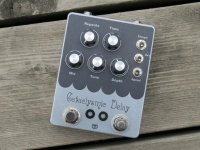
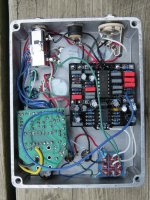
Here's how everything looks right now...
 

Attachments

  • Front(small).jpg
    Front(small).jpg
    207.7 KB · Views: 34
  • Inside(small).jpg
    Inside(small).jpg
    164.2 KB · Views: 37
Back
Top