I'll keep it simple, basically tell you what you need to know without getting into the math any more than is absolutely necessary.
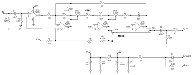
A State Variable Filter (SVF) and a Bi-Quadratic filter are the same thing. An SVF is basically an analog computer that solves a 2nd-order differential equation. Here's one I designed:

U1A is a buffer and is not really part of the filter. I put it there to provide a high impedance at the input and a low impedance driving the filter.
U1D is a summing amp. It combines the input signal (via R3) and two feedback signals via R5 & R7.
U1C and U1B are integrators. They are like low-pass filters with a cutoff freq at zero Hz. U1C's time constant is equal to R*C where R is R8 + the FREQ pot and C is C3. The time constant of the integrators influences the Q and cutoff frequency of the filter. Notice that in this circuit the two integrators are identical and the FREQ pots are ganged together. That's important for reasons I'll get to in a minute.
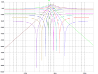
An SVF has three outputs: High-Pass at the output of the summing amp (U1D), Band-Pass at the output of the 1st integrator (U1C) and Low-Pass at the output of the 2nd integrator (U1B). S2 is a DPDT ON-ON-ON switch used to select one of the outputs. It's also possible to get a Band-Reject (notch) filter output by combining the High-Pass & Low-Pass outputs.
I mentioned that there are two feedback paths back to the summing amplifier. The path from the 1st integrator back to the summing amp provides damping. Damping is the opposite of Q. The Q pot controls the damping of the filter.
The reason we gang the FREQ pots on the two integrators is that if the two integrators have the same time constant, then Q is constant for any FREQ setting.
We make R3, R4 & R7 equal to simplify the math. We make C2 & C3 equal for the same reason. When we do this, the SVF's frequency is equal to F = 1/(2*pi*R*C) where R = FREQ pot + R8 (or R9) and C = C3 = C4. The filter shown above can be tuned from 72Hz to 7.2KHz. The Q calculation is a little more complicated. Making the integrators equal and all of the other resistors equal simplifies things immensely. I made R = R3 = R4 = R6 = 10K and Rq = R5 + VR2. Then we end up with Q = 1/2 + Rq / (2 * R). Rq varies from 15K to 265K. When the Q pot is at max resistance, Q = 1/2 + 265K/20K = 13.75. When he Q pot is at min resistance, Q = 1/2 + 15K/20K = 1.25.
For pedals, the practical limit for Q is around 20. There are three reasons for that.
1. High-Q filters require precision components. The least precise component in the SFV is the dual-gang pot. Dual-gang pots do not track very well and any imbalance can cause the Q to vary. If the Q gets too high, the filter can break into oscillation.
2. The gain of the filter at resonance is proportional to the Q. If the Q gets too high we can run into headroom problems.
3. Filters with Q over 20 just don't sound very good (IMHO).
The Tychobrahe ParaPedal contains an SVF. Some envelope filters, such as the Mutron III and Maestro FSH-1, contain SVFs.
That's about it.
If you want to get deeper into the details,
there is a good article here.


