Silver Blues
Well-known member
- Build Rating
- 5.00 star(s)
[Copy-paste of intro blurb from the last time I did this:] I've been at the pedal building game for quite some time now, and I feel like I've come a huge way from my dad helping me solder up my very first Big Muff (love you, Dad) wherein I overpaid for every component, didn't understand the concept of positive ground and built it with 2N5087s, and burdened it with a completely shit purple rattle-can paint job. After having discovered the magic of PCBs, UV printing services, powdercoating, etc., seeing some of my more recent builds next to the older ones was making several of the older ones look pretty sad. With that in mind, I thought it might be a nice exercise to revisit a few of my older builds with a fresh, more experienced perspective, and bring them up to today's version of my standards.
On today's episode, we're talking about the Greer Green Giant, which is a really interesting circuit. On the surface, the Green Giant looks like nothing - an Electra with a diode blend (or, let's say, a warp control) - but even that small change opens up a lot of versatility (this is not news to anyone, it's why we have 1500 "different" Electras kicking around) and it's really a decent sounding circuit. Back in 2014, a vero layout for the Green Giant was posted over at Tagboard FX, to which one builder offered the advice:
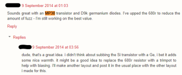
That advice turned out to be a million-dollar idea, and spawned a large community discussion and the eventual development of the "Germanium Giant", a variant of the Green Giant designed to accommodate a full complement of germanium semiconductors. The beauty of that was that almost any transistor and diodes in any combination could be used to similarly pleasing effect in the circuit, and there were lots of contributions from people describing their favourite combinations and modifications to the original. I got bit by the bug as well and was inspired to make my own:
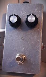
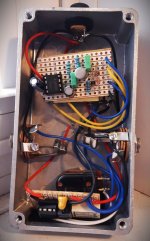
While the pedal sounded great (more on that below), the build itself is embarrassing. The board had come unstuck from its mounting pad (who knows how long after I stuck it there the first time), it's a mess of spaghetti wiring, the jacks are salvaged switched-tip mono for no reason whatsoever, and I stuck it in a badly drilled, raw aluminum enclosure (if you look closely, you can see that the knobs are misaligned). I don't know what 2015 me was thinking with this. The pedal was ripe for an upgrade, and with the relatively recent release of the Jolly fuzz project, I thought it would be timely to share my updated take on the "Germanium Giant", which I'm calling the "Germanium Giant Plus", through the magic of Retrospective:
On today's episode, we're talking about the Greer Green Giant, which is a really interesting circuit. On the surface, the Green Giant looks like nothing - an Electra with a diode blend (or, let's say, a warp control) - but even that small change opens up a lot of versatility (this is not news to anyone, it's why we have 1500 "different" Electras kicking around) and it's really a decent sounding circuit. Back in 2014, a vero layout for the Green Giant was posted over at Tagboard FX, to which one builder offered the advice:

That advice turned out to be a million-dollar idea, and spawned a large community discussion and the eventual development of the "Germanium Giant", a variant of the Green Giant designed to accommodate a full complement of germanium semiconductors. The beauty of that was that almost any transistor and diodes in any combination could be used to similarly pleasing effect in the circuit, and there were lots of contributions from people describing their favourite combinations and modifications to the original. I got bit by the bug as well and was inspired to make my own:


While the pedal sounded great (more on that below), the build itself is embarrassing. The board had come unstuck from its mounting pad (who knows how long after I stuck it there the first time), it's a mess of spaghetti wiring, the jacks are salvaged switched-tip mono for no reason whatsoever, and I stuck it in a badly drilled, raw aluminum enclosure (if you look closely, you can see that the knobs are misaligned). I don't know what 2015 me was thinking with this. The pedal was ripe for an upgrade, and with the relatively recent release of the Jolly fuzz project, I thought it would be timely to share my updated take on the "Germanium Giant", which I'm calling the "Germanium Giant Plus", through the magic of Retrospective:
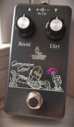
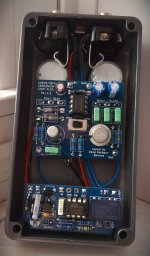
Sorry that the build report for this pedal is delayed by a few months because I made a boneheaded mistake on the first batch of PCBs, and both pots worked backwards, requiring me to reorder boards, disassemble and reassemble the whole thing. (For eagle-eyed readers: this is what was in my first-ever JLC blue box!) First off, I've modified the circuit in a few ways, to address some issues and increase convenience. Firstly, there is an ICL7660S-based polarity inverter on board, and the builder can have the board accommodate NPN or PNP transistors at the flip of a simple slide switch. This maintains the ability to use the originally-specified MP38 transistor (an NPN device) if desired, but also allows the builder to tap into the much larger stock of good PNP germanium devices still out there. The most significant problem with the original Germanium Giant is that there is a substantial volume loss when the diodes are fully "on" - barely above unity. This version adds a second gain stage after the original "Green Giant" circuit block to recover the lost level. It's not just a clean gain stage, though - it's 80% of another Green Giant, with the caveat that the emitter resistor is not sent to ground but rather to the opposite power rail, so we gain a little bit of headroom.
The beauty of this circuit, the variability of using whatever components you like within certain broad limits, is retained. The diodes can be anything germanium, Q1 can be [almost] any germanium device you like, and Q2 can be any BJT at all (germanium or silicon). With a germanium Q2 and the diodes fully "off", the tone is not "clean" as you might expect from a regular Green Giant/Germanium Giant, but the bipolar power on Q2 helps it not get into crazy drive territory under these conditions (which is not desired). A silicon Q2 keeps things much cleaner at low values of the diode blend. I also adjusted the diode blend control in two ways: 1) it works oppositely to the standard Green Giant (turning it up turns on the diodes more, and so I've labelled it "Dirt" instead of "Clean" or "Blend"), which I thought was more intuitive, and 2) I have specified a B10K instead of the original B20K or B25K because I found this gave a more useful sweep.
I simply scavenged my old pedal to supply some of the parts for my personal build shown above. I chose a 2SA49 (42 hFE, 14 uA leakage) as Q1, an MP16B (14 hFE, 20 uA leakage) as Q2, and real vintage 1N34As from my dad's ham radio repair parts stash for the diodes. I chose to use 330nF coupling capacitors for low-end retention without blowing out the bass frequencies. Relay bypass comes courtesy of @MattG, who was kind enough to send me several of his lovely bypass modules in exchange for a long-term quality evaluation; this build contains his V1.0 module. So far so good!
The graphic, which might be recognizable to some of you, is a stylized frame from The Iron Giant (1999) where I edited a geranium into his hand ("Germanium?? oh, I thought you said "geranium"... you get it) and made the indicator LEDs his eyes. The title is rendered in a super cool font called "Dragon Is Coming", and the rest of the labels are Footlight MT Light. The knobs are some old bits from Tayda that I swiped from the original pedal because I actually liked them and wanted to reuse them. The graphic was printed at Tayda on a Pearl Grey 1590B. It was a tight squeeze for sure, but I did manage to get top jacks into a 1590B!
So how does it sound? I chose the 2SA49/1N34A combo for the original pedal because I liked the deep, smooth drive tone you could get out of them. This pedal is amazing for bass because you can blend in subtle drive without blending in your unaltered clean tone, which sometimes conflicts with the wet tone. This works doubly well with the bit of intrinsic drive you get from having Q1 drive a germanium Q2, and I chose the MP16B purely because of how well I thought it complemented the other two component choices. You can get A LOT of different tones and feels from this circuit just by changing the semiconductors. I didn't include any bias trimmers on this board because I found that the "stock" Q1 collector and emitter resistor values worked well for almost every transistor you could stick in there, with one exception - AC125/AC128 do NOT make good Q1s; they're very fuzzy and gross-sounding unless you take the collector resistor down from 47K to 10K or less, and even then don't have the most pleasing tone, so I would recommend avoiding these. On the other hand, those same devices make excellent Q2s.
I plan on sharing the gerbers and build documentation for this project on my website (see link in my signature) at some point in the near future, I'm just still working on some other stuff I want to put up at the same time. This batch of boards has a typo on the silkscreen, but I've fixed it and the uploaded gerbers will be corrected.
A lot of the ideas that went into these mods were proposed in the linked thread from Tagboard above, so I don't want to take too much credit, I just consolidated them with my own spin into one variant.
Last edited:

