You are using an out of date browser. It may not display this or other websites correctly.
You should upgrade or use an alternative browser.
You should upgrade or use an alternative browser.
Rounded edges on PCB
- Thread starter Jiberjew
- Start date
Nostradoomus
Well-known member
Make your board outline, then right click and go to "board points"
There will be a few boxes to tick on the bottom left, click "create RoundRect board" and size it out from there with height/width/radius of arcs.
There will be a few boxes to tick on the bottom left, click "create RoundRect board" and size it out from there with height/width/radius of arcs.
Jiberjew
Member
Awesome! I knew it would be something super easy! Worked out great.Make your board outline, then right click and go to "board points"
There will be a few boxes to tick on the bottom left, click "create RoundRect board" and size it out from there with height/width/radius of arcs.
Thanks for the tip.In Eagle I always did the radius last, but in Diptrace it seems useful to do it early, because the outline shifts leftward by the radius amount. But you can fiddle with the points themselves too.
Jiberjew
Member
All worked out great! Got 4 PCB’s under my belt now. Went from knowing nothing but non-related audio electronics to designing a few PCB’s! I was on the fence if I could actually do it, but everyone here got me through it! I’ll post my builds real soon. Now I have to take advantage of the 15% off pedalPCB has. Thanks a ton everyone!
Smrtokvitek
Well-known member
I add points next to a corner in a distance of a radius I want and then change the corner point to "arc" in the properties (right click and board points) and set the radius to the desired value.
Robert
Reverse Engineer
I round mine manually as well.
It's just too much of a hassle to follow a calculated contour accurately when working on multi-board panels.
My method is similar to @Big Monk, up until the last step.
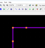
I create points 0.075" from the corners.

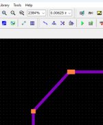
Then switch my grid to 0.00625" and drag the corner over so it's one grid point (.00625") from the other point.

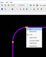
Then right click the corner point and click Arc.

Doing it this way makes it MUCH easier for me to follow that radius at a specified distance for things like panelized boards.
I don't like dialog boxes.
It's just too much of a hassle to follow a calculated contour accurately when working on multi-board panels.
My method is similar to @Big Monk, up until the last step.
I create points 0.075" from the corners.

Then switch my grid to 0.00625" and drag the corner over so it's one grid point (.00625") from the other point.

Then right click the corner point and click Arc.

Doing it this way makes it MUCH easier for me to follow that radius at a specified distance for things like panelized boards.
I don't like dialog boxes.
Jiberjew
Member
Perfect! This is exactly what I was trying to do! I got some good tips yesterday and tried it out. I was happy with the result, but wanted to round out more areas of my PCB. Thanks for the help! This will work out great!This but also you can also shape the board in many ways.
I almost always use 0.635 mm as my standard “bump” measurement. My rounded corners are then as follows:
View attachment 79127
Select Object -> Board Points, then select the "corner point":
View attachment 79128
I use 0.635 mm and have my other points 1.27 mm away from the corner. Then select Arc and change the value from 0.898 mm to 1.27 mm:
View attachment 79129
I do a lot of this manually because I use non-standard board layouts:
View attachment 79130
Totally agree with this! I tried this method and it’s WAY easier, and faster. Thanks for the write up. You’ve saved me multiple times!I round mine manually as well.
It's just too much of a hassle to follow a calculated contour accurately when working on multi-board panels.
My method is similar to @Big Monk, up until the last step.
I create points 0.075" from the corners.
View attachment 79131
Then switch my grid to 0.00625" and drag the corner over so it's one grid point (.00625") from the other point.
View attachment 79132
Then right click the corner point and click Arc.
View attachment 79133
Doing it this way makes it MUCH easier for me to follow that radius at a specified distance for things like panelized boards.
I don't like dialog boxes.
Jiberjew
Member
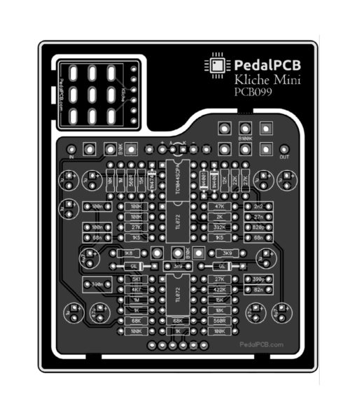
This is definitely something I’d like to do. This will save a lot of time and money for sure. I’ll have to do a bit more research to see exactly how to get the cutouts. Eventually I’d like to design a PCB with all components being mounted to the board. But, geting the basics down right now. Thanks for all the help and tips!The cutouts on panels like this are all drawn manually... you need full control over the curves in order to trace around the board outline and flow around other breakout boards smoothly.

Robert
Reverse Engineer
It actually doesn't save money... The panelized Kliche PCB costs slightly more than the two PCBs individually, but it makes it easier to keep up with the breakout board and ensure I don't forget to ship it. It pays for itself in the long run, plus it looks nice. 
You can sometimes save money by panelizing duplicates of the same layout, but not always. It's the most cost effective on tiny PCBs like breakout boards.
You can sometimes save money by panelizing duplicates of the same layout, but not always. It's the most cost effective on tiny PCBs like breakout boards.
Jiberjew
Member
Got it. I’m only planning on selling pedals, not PCB’s (hopefully haha). In that case, I’d only do that for switch breakouts. Makes sense, the larger the board, the higher the cost. JLCPCB has been pretty good so far, as far as cost goes. And the PCB’s have been pretty decent. Thanks again!It actually doesn't save money... The panelized Kliche PCB costs slightly more than the two PCBs individually, but it makes it easier to keep up with the breakout board and ensure I don't forget to ship it.
You can sometimes save money by panelizing duplicates of the same layout, but not always. It's the most cost effective on tiny PCBs like breakout boards.
Similar threads
- Replies
- 10
- Views
- 585
- Replies
- 4
- Views
- 734
- Replies
- 7
- Views
- 423

