BuddytheReow
Breadboard Baker
Hey guys,
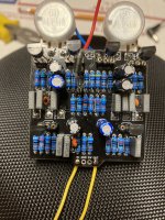
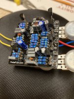
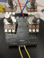
Just finished the circuit on a sabbath distortion. I alligator clipped it to test and I get virtually no signal coming through. The signal that does come through is incredibly faint and sounds not distorted. The pots appear to sound correct (volume, gain, etc). I did test the pots before soldering them in. Here are the voltages for the trannies, pins reading left to right:
q1 0 2. 8.7
Q2 0. 1.6 3.7
Q3 2.9 4.8 8.8
Q4 0 0.6 4.2
Q5 2.9 5 8.8
Q6 2 5 8.8
Any assistance would be greatly appreciated. I know I can count on you guys to help with this.