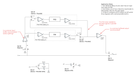
Hi All. I have two Magnetron PCBs that I'd like to wire together with the ability to switch between series/parallel. Below is a sketch of what I'm hoping to achieve. Each PCB has input/output buffers and level/blend control of the delay (see second image). Do I need the common input and output buffers shown to ensure impedance matching? Or can I safely delete them since both PCBs have buffers and phase? Are there any other issues that I'm not considering with the concept below? Any and all feedback is appreciated. Thank you!


