Check my diagram? Series/parallel switch

Pauleo1214

Well-known member
Hey y'all. I am planning one of my stupid combo builds with circuits in parallel in the send/return loopnof a buffer. I want to include the option to switch the two pcbs to series.

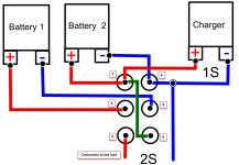
Would the wiring in the diagram below work? Any input and verification would be appreciated! DTDT-Switch-2S-Battery-parallel-Charging-series-use.jpg
 

Attachments

  • DTDT-Switch-2S-Battery-parallel-Charging-series-use.jpg
    DTDT-Switch-2S-Battery-parallel-Charging-series-use.jpg
    100.6 KB · Views: 1
I'd like to try to help here, can you confirm that this is what you're trying to achieve?

You'd like to go from this:
1702681534687.png

To this:
1702681561232.png

On a DPDT ON-ON switch, is that correct?
 
Cool, it's actually pretty simple.

You'd wire your switch as follows:
1702681803166.png
Pay close attention to the tags, the I/Os for the effects are re-ordered compared to the previous images. Switch pins are labeled in the schematic.

You could optionally add an indication to the switch setting by going with a 3PDT as follows:
1702682397568.png
 
Back
Top