foaminginfection
Member
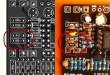
Hi everyone, I am new here, but I recently bought the Sherwood PCB and got to building it. I am meticulous about how I go about building and noticed a discrepancy between the diagram downloaded from the internet and the actual PCB. It has to do with capacitors C9 and C14. On the printout, it says that C9 = 100n, C14 = 4n7. And this matched the image used on the site of what the PCB looks like. However, the PCB I received has them switched. I followed the PCB rather than the printout. Can you tell me which is correct and why the hell this is not fixed?
Follow-up question: is the fact that I am using primarily ceramic capacitors going to mess things up?
Follow-up question: is the fact that I am using primarily ceramic capacitors going to mess things up?

")

.png")