burger-patty-and-bacon
Active member
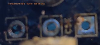
First off, what is the silver stuff around the "traces" called? Are they called "PADS"? Solder rings? What is the non idiot way to refer to that?
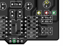
On my melter, I f'd up (but learned a lot!) and had to redo the pots, one of them more than once. The one that really got me was the BOOTY pot which is a C5K.
On what I call the component side it has the 3 "silver pads" which are still ok. However, on the back side, one of the pad things is basically fubar and gone. IS IT OK TO HAVE ONE SIDE of the pad thing missing? Here are pics to help explain what I am asking about.