Six String Stinger oddness

Allthumbs

Active member
This is my 3rd pedal, first one from pcb alone, the others were complete kits. this one went pretty well but acts weird.

1. it's really quiet. my J201 were around .36 ma each so I suspect this is why. I have since found higher value ones to buy so I'll try that if someone can verify that this may be the issue...

2. the filter pot acts weird in that it doesn't really do much. I think I read about using an audio taper here instead of linear but I'm not sure. I hear it change the tone but not much at all. maybe the volume need to be an audio taper as well? again, not sure.

mainly the volume is fairly low, at about 3/4 full it's at unity where by reports of this design it should be loud as hell.

some help would be greatly appreciated.

I built 2 of these way back when & they have plenty of Volume, where did you get the J201's, What Markings are on them?
The Filter is Subtle, Clockwise is cutting Bass, CCW it cuts Treble
Can you post a Picture of the Build clearly showing the Resistors.

Here are some Fairchilds: https://www.pedalhackerelectronics.com/JFET-J201-Fairchild-FSC-p/j201-10.htm
 
thanks for the reply. I got the 201 from mouser I believe. View attachment 453
Resistor values look Good, I'm still leaning towards the J201's , they can be prone to Heat damage by Soldering.
Don't Solder all 3 legs in a row, this also includes Pots, Toggle Switches, Footswitches ect.

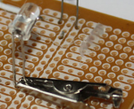
One good method is to put an alligator clip on the leg as you solder.
This absorbs the heat instead of the component :

454
 
You could always lower the source resistors on Q2/Q4 (R8/R14) to increase the gain/volume. Lowering R8 would increase the gain, lowering R14 would increase the volume. You might want to lower both. This might be easier than replacing the J201s.
 
You could always lower the source resistors on Q2/Q4 (R8/R14) to increase the gain/volume. Lowering R8 would increase the gain, lowering R14 would increase the volume. You might want to lower both. This might be easier than replacing the J201s.
Nice, thanks for that. would I step down just a bit or drastically? R14 is 10k, so maybe 5k?
 
10K to 5K sounds like a reasonable thing to try. you could temporarily solder the long leads of another 10K resistor on top of the 10K one already on the board to see what a 5K resistor would sound like. try to save removing and replacing the one on the board until you know what final value you want to use. the PCBs can be fragile when removing parts, so it makes sense to limit the number of parts that are removed and replaced.
 
I have to say that I've gotten used to the pedal as is, volume cracked rather high is sort of in a sweet spot and drives other drives nicely. just a bit increase would be nice on both Vol & G. BTW, I ordered "high gain" Siliconix J201's from Small Bear and they were not. exact same as the last.
 
if you like the way it sounds as is, and you are not turning it all the way up and wishing it went to 11, maybe you don't need to change anything. it still seems like the pedal is supposed to be louder than it is right now, but if you would still end up setting it near unity, it may not make any difference in how it works when you are playing.
 
It;s just above unity right now at about 3 o'clock on the V. Gain is low up to 3'oclock as well. I may boost the volume as you suggest after another practice with it.
 
I was also wondering what mod might affect the tone circuit to get more frequencies at either end. I'm imagining this is constrained by a resistor as well? I can't read a schematic but I'd guess R15 or R17? Maybe that C11 has something to do with that?
It would be nice if it got brighter or could switch it into a bright setting similar to the "glass" setting on the Duellist.
 
First, I am not familiar with this circuit. Second, you need to be VERY CAREFUL swapping parts in and out of your circuit board, especially if you have not done this before. PCBs can be very fragile when you unsolder parts and remove them from the board. It is not unusual to damage a board when trying to replace a part, usually because a trace from the part gets ruined. Isolating and fixing that kind of problem can take patience and learning even more about how the circuit works. Some people might build a pedal to spec, and then build a second one to do a bit of experimenting with changing the part values. That also makes it easier to compare the new sound to the old one.

Anyway -- with that caution in mind --- look at your circuit diagram where the tone control is and if you don't understand the diagram for the tone pot to see how it works in that diagram, do enough google searching to figure it out.

The pot has 3 lugs that solder to the board, and in the circuit diagram you can you have two paths that go to each "side" of the tone pot, and the middle lug connects to the path where the sound goes out. That means when you turn the pot, it is shifting the output toward one or the other of the two incoming paths. One path goes through c11, and the other one goes through R15.

Since you know that each of those paths must sound different since it affects the tone, I would suggest trying different values for C 11. I would probably try dropping C11 to half that value, and try doubling it to see how that changes the sound on that side of the pot. You could also try changing the value of R15 if you wanted to see what that did to the tonal balance.
 
I tried some of the mods, I mentioned. I ended up with too much gain. However, in the usable range, the sound really became more tubelike and the cleans were better, as well. I'll tweak it for the next week or two and give you an update.
 
Last edited:
Hello, its quite an old thread but I finished my Six String Stinger and although it sounds kind of nice there is very little gain on tap. I noodled around with it yesterday and had to crank the gain all the way in order to get at least a little crunch out of the thing. I already read this thread and added a 2nd 10k resistor to R8 as suggested (so it should be 5k now right?!) but still not a lot of gain. Is this just the way the circuit works or could there be another problem? My J201s are SMDs on adapter-pads so I assume that they should be ok...
 
Back
Top