[SOLVED] Gain knob not responding on Oasis (Dunes)

GregDS

New member
Hi everyone, this is my first post here,
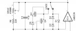
I built a Oasis today but the gain knob seems to be stuck on a certain value. Turning it has no effect on the amount of clipping, I just get a very soft overdrive.
I measured the value of the gain knob (on the circuit but I mostly wanted to see if it was doing its job) and the value is changing as I turn the knob like it's supposed too.
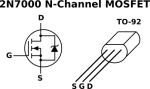
Populated the PCB went smooth, except maybe for the D5 (the LED) because the cathode/anode orientation got me a little confused and I had to remove it and put a new one in the orientation. Could it be something there?
If you guys have any input on where I should start looking, shoot!
thanks a lot

gregDS
 
Hey Nostradoomus, thanks for the quick response!
No I didn't measure the MOSFETS, that's something I definitely have to introduce in my routine a lot more.
BANDWIDTH definitely have an effect, I go from normal response to sort of a bass boost. It's definitely more subtle with the VOICE switch, not sure I'm hearing a noticeable difference.
D5 doesn't light up when I play though, I know on some circuit it's not uncommon for the LED not to light up, I dont know about this one.
All the knobs are working fine, except for the gain, it feels like it's stuck on a fixed value no matter how I turn it

gregDS
 
Alright, I'll try to do that this week.
I'm kind of suspected the LED... Gave me a lot of trouble removing it in the first place, I'm afraid I might have popped the eyelets out...
 
So I checked all the connections (I think) and everything seems fine, including the LED that I thought might have a dodgy solder.
I swapped the opamp with another LM833N, same symptoms.
I didn't check the values of the mosfets because I have the same symptom on every position of the VOICE switch, so either I have simultaneously a defective opamp, defective silicone diodes and the defective mosfets (or bad solders on all of these), I feel the problem is happening elsewhere as the GAIN pot just does not respond in any of the VOICE switch 3 positions, or is my reasoning flawed?
The GAIN pot is showing different values in its course when I measure it, so it's not like the pot is dead, I think.
I just get a very very mild overdrive, can probably use it as a clean-ish boost as the VOLUME and the TONE knobs work fine but yeah, that's not why I built it haha
Thanks a lot for the help

gregDS
 
Have you got a multimeter? Measure the mosfets and transistors and post the results. Sounds like the op amp is fine but measure it too. Did you substitute any parts?

Check for connection and values at C4 and C12 as well....sounds like something in line with your drive pot is open. If it all checks out try a new pot. Post pics too if you can :)
 
Last edited:
Thanks a lot for your reply!
Yes I have a multimeter, I checked the connections using the continuity setting.
Just to be clear, when you say measure the mosfets and the transistors, should I measure them on the circuit? Or do I have to unsolder them and measure them in isolation? And if left on the circuit, should I take measures when it's powered up?
Except for the op amp I did not substitute any part, should have socketed those transistors though...

sounds like something in line with your drive pot is open
yeah it does really sound like that, but I'm not good enough reading an pedal schematic and understanding the role of each components just by looking at where they are in the circuit.
I'll check C4 and C12 as soon as I have some free time and swap the DRIVE pot at some point too if I cant find anything.

Also, I was convinced I posted a picture in my first response to your post but I guess I didn't. It's night over here, so I'll take a picture when I'll have access to a more diffuse light.
 
Yeah power up the board, clip your black meter cable to ground and probe with the red in each leg. Take note of the reading (set DMM to 20vdc) and post the results.

S
G
D
 

Attachments

  • 0AD7ACD8-CE33-4516-A8EE-73F507EDD1DE.png
    0AD7ACD8-CE33-4516-A8EE-73F507EDD1DE.png
    13.9 KB · Views: 6
Thanks a lot for the clarifications,
I poked around in the BANDWIDTH area of the circuit, connections seem good.

For the transistors, the diodes and the op amp, here's what I have:

D1
C: 4.89
A: 4.44

D2
C: 4.44
A: 4.68

D3
C: 4.68
A: 4.89

D5
C: 3.59
A: 4.89

Q3
S: 4.09
G: 4.84
D: 4.84

Q4
S: 4.85
G: 4.89
D: 4.89

IC1
1: 4.85 5: 9.77
2: 4.89. 6: 4.85
3: 4.85. 7: 4.85
4: 0. 8: 4.85

:unsure: what do you think?
Also, figured out what went wrong the first time, file was too big, here you go:
20190930_110135.jpg
 
Man it’s gotta be something silly, only suspect thing is Q4 should look about the same as Q3. Everything else looks just fine.

I’m always suspicious of those little ceramic disk caps (the 47pf) as I’ve had a number of them fail or just a plain not work for me. If you can follow the trace from the wiper (middle lug) of the drive pot to one of the legs of the 47pf cap, gently heat it up and lift the leg out and see what the result is.

Another good plan is to clean that board! Toothbrush and Isopropyl Alcohol does wonders.
 
Hope you don't mind if I jump in here. You have some of the pins scrambled on IC1 and the diodes. Pins 5 & 8 are swapped, so I think you have 6 & 7 swapped as well. Taking that into account, IC voltages look ok. I'm with Nostradoomus, the problem has got to be in the feedback circuit of the 1st opamp. How about we focus on getting it working with the VOICE sw in the middle position? With power off, verify you get 1K when you measure from the bottom end of R8 to the center terminal of the BANDWIDTH sw. You said you measured the DRIVE pot. What values did you get, min and max? Make sure that when you measure it, that VOICE is in the middle, IC1 is out of the socket and power is off.
 
Wow, thanks a lot for the help!

I’m always suspicious of those little ceramic disk caps (the 47pf) as I’ve had a number of them fail or just a plain not work for me.
Bingo! Lifted the leg, plugged it in, worked like it's supposed to! I'll swap the defective one with a good one, but what does that cap do really, because it sounds pretty good without it ah.
BANDWIDTH, VOICE and BRIGHT switch work fine too, nice pedal! Not sure about the BANDWIDTH though, you get such a bass boost that seems to defeat the purpose of a tube screamer-based overdrive. is that something they implemented for bass guitar?

Pins 5 & 8 are swapped, so I think you have 6 & 7 swapped as well
Yes you're totally right, wasn't paying attention, thanks for correcting me.

Nostradoomus, Chuck D. Bones, DGWVI, thanks a lot for directing me in the right directions.
Daaang that pedal sounds good :D
 
Nostradoomus, you called it!

That cap in the feedback loop performs several functions. As DGWVI says, it rolls off some of the high end for a smoother sound. And not just the audible portion of the high end, it also helps to prevent the opamp from acting like a radio receiver. A cap in the feedback loop improves the opamp's phase margin, reducing the tendency toward high-freq oscillation, particularly with large feedback resistors. I recommend leaving it in, but make sure you have a good batch (test them) and buy from reputable sources.

As for the BANDWIDTH switch, if you find the "deep" setting too bassy, but sometimes want to go deeper than the "normal" setting, you can reduce the value of C12. The stock values sets the corner freq at 16Hz. I'd try 1uF for a 160Hz roll-off. That's one of the (many) advantages of building your own pedal: easy customization.
 
I’ve had nothing but bad times with those little bastards haha, well the Tayda ones anyway.

Apparently if they fail both pins short together, and I knew it had to be something connected to the wiper of the pot. Glad it got sorted!
 
A cap in the feedback loop improves the opamp's phase margin, reducing the tendency toward high-freq oscillation, particularly with large feedback resistors. I recommend leaving it in, but make sure you have a good batch (test them) and buy from reputable sources.
Alright, great info here, thanks!
I usually buy my stuff at Banzai Music in germany, I've had a couple of issues with them but nothing that seemed to me out of the ordinary in the electronic world. I would not have suspected a ceramic cap.
I'll definitely be more careful testing caps and transistors before soldering, it's time consuming but still cheaper than build a circuit, not finding what's wrong, throwing it in the drawer and forgetting about it.

As for the BANDWIDTH switch, if you find the "deep" setting too bassy, but sometimes want to go deeper than the "normal" setting, you can reduce the value of C12. The stock values sets the corner freq at 16Hz. I'd try 1uF for a 160Hz roll-off.
Yes I was thinking doing that, maybe even go for a smaller value for the BRIGHT switch too, I play a Gibson Les Paul in drop b...

Apparently if they fail both pins short together, and I knew it had to be something connected to the wiper of the pot
Yeah, I had the feeling something was preventing the pot from doing its job, was missing the knowledge and technicalities that translated that assessment into something useful in the real world ah.

Again, thanks a lot for guiding me.
How can I edit the title of the thread to [solved]? (if that's something you folks do over here)

gregDS
 
Back
Top