SOLVED - Mod a treble booster

boji

Active member
Hi,

I don't know if it's OK to post here about pedals that aren't based on a PedalPCB PCB. If not, don't hesitate to just delete this one.
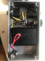
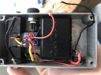
I have a treble booster that I really like that doesn't feature an LED or 9V plug.

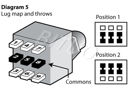
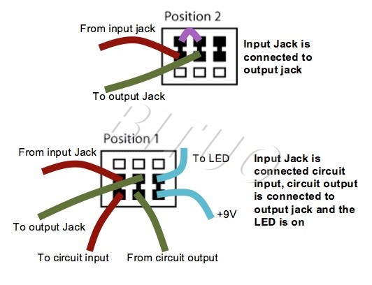
I don't have access to the PCB (which is enclosed in a plastic box) and I'm not familiar with DPDT switches. (see picture)
Can you tell me where to wire the Led and 9V plug?

Thanks a lot!
 

Attachments

  • IMG_4866.jpeg
    IMG_4866.jpeg
    1.2 MB · Views: 16
Replace the 2PDT with a 3PDT; you can directly transfer the wires over to the first two poles of the 3PDT and use the third pole for your LED.

You'll need a current limiting resistor for the LED; you'll power it by tapping off the voltage coming from your modded battery-clip/power jack. Speaking of which...

Leaving a couple of pig-tails, snip the battery clip and wire up the jack, then re-wire the battery clip to the jack as per instructions easily found online in many permutations.

Here's a good place to start for both the bypass and the power:
^ bypass
^ power


Good idea to get some extra wire (black & red) and some heat-shrink tubing — so you'll have enough slack to wire everything up properly and not have anything short out.

Where you drill for the LED and power-jack is up to you, but make sure each one doesn't interfere with other wires/components.
 
I wired the 3dpt switch, the 9v plug and the LED. Everything works fine when the pedal is on, but I’ve got no sound in bypass.

Where could the problem come from?
 

Attachments

  • E280A874-C15A-4071-88E6-283AAF5C92C2.jpeg
    E280A874-C15A-4071-88E6-283AAF5C92C2.jpeg
    252.2 KB · Views: 9
You probably missed the jumper between lugs 3&6.

Sorry didn't see the pic, hang on a tick...

Okay, the COMMON is the middle lug in each pole. You've got to wire the common to the jacks.


Search the web for 3PDT wiring diagrams, many will have the LED pole sandwiched (which means bypass jumper from lugs 3 to 9). Whether you have the LED pole in the middle, left or right... the INPUT pole has to have the jack wired to the middle lug, similarly the OUTPUT pole has to have the jack and middle lug connected.

Just swap the middle and outer lugs' (non-jumper side) wires for each pole and you should be golden.


Note the numbering of lugs on poles (L-R) A, B, C (or poles # 1, 2, 3); note the connections in position 1 and 2:
2.jpg

4.jpg
Pics courtesy of www.bituoelec.com


Now you also know how to wire up a mute switch or stutter-stomper. ;)
 
Last edited:
Hi Feral Feline, the jumper is in place. I resoldered everything on another switch, just to make sure, and took extra care.
 
Hi Feral Feline, the jumper is in place. I resoldered everything on another switch, just to make sure, and took extra care.
Hmm I was editing my post while you were posting, but I didn't see your post during my editing.
I'm guessing you repeated the mistake on the second switch.
Check my edits...

It may help to flip the sw 180º while you've got the wires off it, so that when you re-solder the lugs closest to the "module" get the circuit's wires and jumpered lugs are closest to the jacks. Then the LED Pole will be on the same side as power as well.
 
rezlwgdg5h731.jpg

[EDIT: NOTA BENE!!! THE LUG-NUMBERS ABOVE ARE "INCORRECT" COMPARED TO STANDARD PRACTICE!
Should be (IMO):
1 4 7
2 5 8
3 6 9
So difficult to find simple clean clear correct diagrams 😾 ]

Shortest distance between two points, switch to circuit, and the signal paths are separated by the LED pole for less chance of crosstalk interference.


Many ways to skin a cat...

44250b3cd7cba7cbe6242acacf5218ed.png


More out there, but this post's top pic is the most common that I've seen. [Incorrect numbering notwithstanding]
 
Last edited:
And... That was it! Thanks so much. There are so many 3DPT pics out there that I got confused and missed what was essential. Add the "mystery module" and I was perfectly lost ahah.

Your diagram 5 made it all clear. Thanks!

(And yes, I posted before seeing your edit)
 
Back
Top