SOLVED Son of Ben first build issues

Vinnyallen

New member
I know this is probably a very beginner question but I’m having trouble figuring out where to start with debugging my first build. I just finished up my first pedal. Plugged it in and had sound in bypass. When activated the led comes on but no sound. Where should I start looking? Thanks in advanced
 
You can Google "Troubleshooting my Pedal Build" will give you several video's, post close up photos of both sides of your board here, most noob issues are soldering if your solder joints don't look like tiny shiny Hershey kisses then you need to reflow them, and verify all your component values
 
Where did you get your J201? Did you bias them? Give this thread a good read.

 
You are going to need to provide us with some pictures of the front, back, and offboard wiring for us to provide much help. They need to be clear enough that the resistor values can be read and that the soldering can be inspected.
 
Here are some photos of my build. My guess is that my solder joints are not great and I need to reflow them.

Would not biasing the J201s cause no sound? To be honest I wasn't sure how to do it so I adjusted them based on another build that I saw (again I'm a noob). I'll do some research on how to do that correctly.

I got the J201s from amazon.

The build functions the same in and out of the enclosure. I read that the dc jack I used can cause grounding issues inside the enclosure but I dont think that is the case here.

How bad are these joints? should I start fresh or is it salvageable?
 

Attachments

  • IMG_1030.jpg
    IMG_1030.jpg
    429.1 KB · Views: 34
  • IMG_1031.jpg
    IMG_1031.jpg
    498.1 KB · Views: 35
  • IMG_1032.jpg
    IMG_1032.jpg
    502.2 KB · Views: 36
  • IMG_1033.jpg
    IMG_1033.jpg
    478.5 KB · Views: 37
  • IMG_1026.jpg
    IMG_1026.jpg
    807 KB · Views: 32
The overall suggestion I have is that this is your chance to learn to use some basis troubleshooting skills and tools, even though your instincts for a first build might be that you just want to find a quick fix to make it work and close it up.

Was this a kit or did you track down the parts yourself? That is good to know because you will need to double check and make sure you have the right value parts put in the right places on the PCB. For a first build, your chances of having used the right parts are a little better if you had a kit.

Do you have a digital multimeter (DMM)? If you don't, you should get one. If you already have a DMM, you will need to be able to use it to measure when you have connections between two points, measure voltage in a circuit, and measure the resistance between different points on the board. You can find a number of youtube videos to walk you through the basics.

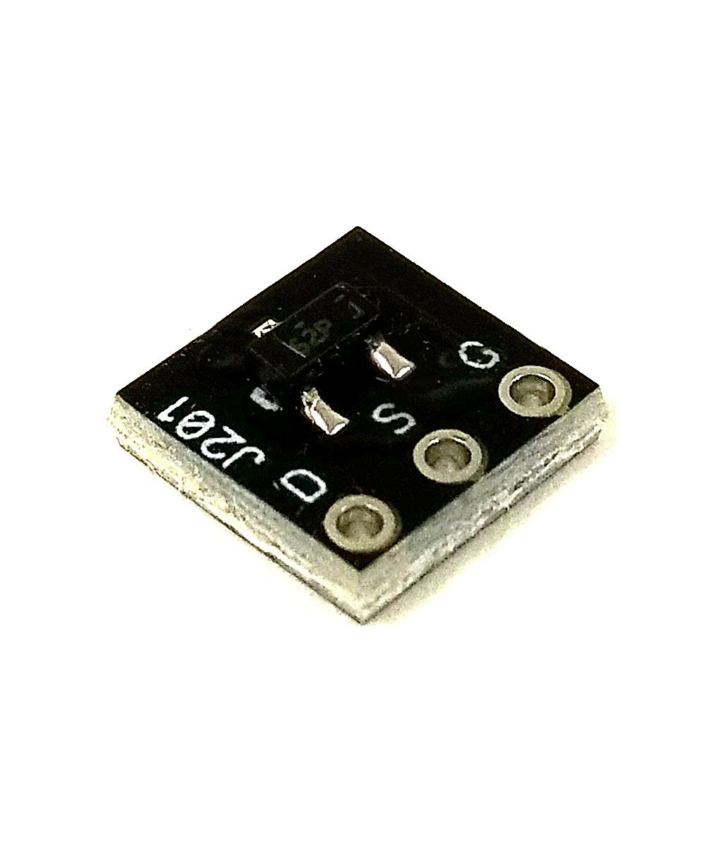
The J201s from Amazon also might be suspect, since that part is out of production and some people are apparently selling bad ones. But you should be able to make sure the rest of the PCB is OK before you need to decide if you have bad J201s.

Go ahead and do a google search on how to build and use an audio probe. that will come in handy. do you have a print out of the schematic for your pedal? Do you know how to read it to identify the parts in the schematic and then find those same parts on your pcb?

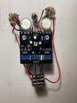
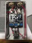
Your solder joints look like they need a bit more solder to me but most of your connections are likely OK as is.
 
Totally agree.

I tracked down the parts myself from Tayda and I used a multimeter to verify the values before using them.

Good to know about the J201s. I have some other 2N5457 transistors that I could use. But I'll wait and rule everything else out first.
 
The audio probe may be the quickest tool to let you know how far your signal is going through the parts on the pcb. Also easy to put one together with a small number of parts.
 
I built a probe and tested. Everything is good until the signal reaches the first J201. After there is no signal at all. Any ideas? I used my multi meter to test the connection. With the positive on the source and negative on the drain it reads 850. With positive on the source and negative on the gate it also reads 850. After watching a handful of you tube videos I am still stumped
 
zgrav has told you everything that needed to be addressed.
You need to tin ( Solder) your wire before you attach it to your PCB'S or Jacks!
I would suggest getting wire that is already Tinned!
The 2N5457 will work but where J201's are required, That's what you need for the Circuit to work Efficiently.

PedalPCB sells these as J201's are not in production anymore in 92 package
You just need to solder 3 legs onto the Board to mount them to the PCB.:


Happy Soldering!!!
 
By switch you mean unsolder and replace with a new transistor right?
Try adjusting Q1 trimmer while plugged in to see if you get any signal with the Audio probe.
Adjust Trimmer by ear to the loudest noise comes from it.
Repeat by Ear Q2 & Q3 until Trimmer finds loudest signal.
If it works & they are not in the 4.5v to 5v range, They are out of spec or Fakes.
Try the 2n5457 in Q1 at 4.5v & if it gets Signal, The J201's are no Good !
 
Update:
It's working!! I definitely had fake j201s. I ordered some j201s from pedal pcb and redid the entire board. I wasn't able to remove my 6 prong bass pot from the board. Luckily I had enough components and another board so I could make a second.

Fired up right away. Just need to adjust the trim pots. Thank you all for your help!
 

Attachments

  • IMG_1045 (1).jpg
    IMG_1045 (1).jpg
    748 KB · Views: 25
Back
Top