Son of Ben: let more bass through?

jrhevron

Member
I built the SOB a year ago, but it's just not getting a lot of use on my bass board as it cuts too much bass frequency.

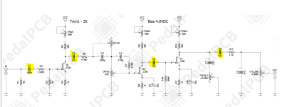
Would changing C1 to 1UF be enough? It's currently 100n.


EDIT: I ended up switching out C6 and C8 for 330n (what I had on hand, though I think anything 100n and above would have been fine). That really opened up the pedal and makes it sound a lot fuller and more useful on bass
 
Last edited:
You'd want to look at the other deoupling caps as well and up their values. IMO if you tune this for Bass it may not sound good on guitar. You are seeing the opposite right now. Your best bet is to socket the components or attempt to breadboard it and tweak to your liking.
1654543270517.png
 
That makes sense... I'm not interested in making it work for guitar, only bass... so totally not worried about tweaking it. I changed the coupling caps on my muff, so maybe I'll just go that route here to make it more useable.

Do I need to change the resistors that follow?
 
No, just change all the highlighted capacitors. You should compute all filter corner frequencies for each stage to get the right value, or you can just go by trial and error, like start with doubling all the values.
 
No, just change all the highlighted capacitors. You should compute all filter corner frequencies for each stage to get the right value, or you can just go by trial and error, like start with doubling all the values.

Thanks @giovanni!

I know nothing, but I did find this corner frequency calculator: https://www.omnicalculator.com/physics/cutoff-frequency#how-to-use-the-cutoff-frequency-calculator

When I plug in the cap and resistor values... what cuff frequency am I looking for?
 
This is the calculator I use, but they all pretty much do the same thing.

Many circuits out there clip off the super high (think 10k Hz+) or super low (under 25-50 Hz) frequencies. This is done to prevent unwanted noise from being amplified. Many guitar specific circuits clip the bottom end off to reduce the amount of muddiness. The smaller the decoupling cap or input cap, the more bass gets dropped. Off the top of my head, I think bass frequencies range from 100Hz-3k Hz.

I'm saying this because you'll need to find the right balance. Sockets or a breadboard are your best bet here.
 
A good starting point would be changing the input cap to 1uf and the decoupling caps to 100n and go from there. Those are some ballpark values to start with

Thanks for this! I've learned something tonight. Gonna give it a shot.

Have you tried the mod to remove C5 for more gain before breakup on the drive knob?
 
Thanks for this! I've learned something tonight. Gonna give it a shot.

Have you tried the mod to remove C5 for more gain before breakup on the drive knob?
I should come clean and say I've never built this specific circuit with solder or a breadboard. What I do know, or should I say have learned, from my breadboarding time or circuit analysis education via Google, is that removing c5 or c10 will actually decrease the amount of gain. You can try upping the caps values to, say, 22uf but there will be diminished returns since it will get noisy rather quickly. 10uf IMO is the sweet spot.

If you're interested in any theory you should check out the resources thread in the Test Kitchen here. There's a lot of good stuff. I also documented a lot of my findings and experiments (A bit more beginner friendly) here
 
The problem with the corner frequency calculator is that you have to figure out the equivalent resistor for each stage to plug into the R value. The resistor value will depend both on surrounding resistors and on the transistor bias point and configuration. In short, it’s not trivial and you would need to do a lot of analysis. Alternatively you can plug the circuit in a simulator (like spice or partsim) and let the software tell you the bandwidth. That’s also an easy way to check how different component values affect the frequency response. Keep in mind that once clipping or distortion kicks in, the frequency analysis goes out the window and you may have to do transient analysis.
 
I ended up switching out C6 and C8 for 330n (what I had on hand, though I think anything 100n and above would have been fine). That really opened up the pedal and makes it sound a lot fuller. At least on my bench rig, it sounds great! I rebiased the JFETs as well. I did that correctly when I built it, but things were a little off there at this point. It sounded much better after that as well, though I wish that the OD was a little bit smoother. I'm going to go in and tune the JFETs by ear (3 to 2 to 1) to see if I can smooth things out a little bit. If not, I can always go back and rebias it to spec with my meter.
 
Just messed with the biasing a little bit. I'm able to fine tune it some, but it's not so far off with the provided values. I wish that I could get it to be a little less spiky/splatty but I need to test it through a real world amp to actually see what it sounds like. Just put it back to production values and took off C5. I like it a lot now!
 
Last edited:
@jrhevron — here's another calc:

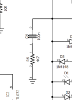
@Feral Feline what numbers do I want for bass? For example, in the below from the Greengage OD, I replaced C4 with 400N

As is, the freq is 339hz (according to https://rc-calculator.glitch.me/)

Change to 400n and the freq is 85hz, which is too low sounding.

I'm still not sure what this means... it's a high pass filter, so is it cutting all freq below 85hz? That doesn't make sense, does it?
 

Attachments

  • Screen Shot 2022-06-10 at 11.38.46 AM.png
    Screen Shot 2022-06-10 at 11.38.46 AM.png
    14 KB · Views: 4
If you don't have the right cap you can also adjust the value of the resistor. Lowering the resistor value will raise the cutoff frequency. SInce this is a high pass filter it will allow frequencies ABOVE the cutoff to pass through

I'm assuming that's in the opamp feedback loop. You need a RC filter to "tell" the opamp what frequencies to amplify. If wont work without it; I've tried it on a breadboard.
I think it is in the opamp feedback loop... so that's interesting because the circuit is now amplifying too much of the low frequency. That makes more sense now.

I wish I could breadboard this one, but I'm just not there yet and don't have time to figure it out now. Someday!
 
@jrhevron Sockets are your friend until you're comfortable with breadboarding. However, it's a bit lazy (socketing) and if you want to do lots of mods you end up with too many components socketed and if one component is not sitting correctly in the socket ... well, let's just say debugging can be a bitch.

So I suggest do as I suggest, not do as I did do, which was relying far too much on socketing instead of just getting familiar with the breadboard. It's really not that hard — if I can do it...


All those online calcs do is tell you what the corner freq is. The position of RC to CR tells you whether it's a high-pass or low-pass and so long as you can determine signal flow you'll know which is which, which to use etc.

Above all, trust your ears. Something works for you, your gear, then it's good. If you play a P-Bass and love the sound, what does it matter if your guitar-twanger friend says it's "too muddy" with his/her humbuckered-LP.

YOU said it was too muddy at 400n, so back off to 330n if you've got some and then 220n...
If you don't have a value you want here's a couple of ways to cheat towards what you're after and or get in-between Goldilocks' settings of "just right":

400n in series with another 400n will get you 200n!
It's the opposite of series resistors that sum (200k + 200k= 400k)

400n in parallel with another 400n will = 800n.

Use this calc to figure out what you'll get exactly:

The calc is for resistors, but works for caps, too; it's the same math just opposite for capacitors.

For instance, 220n + 330n series = 132n


Also, the "elbow" varies with how you achieve the corner frequency, but nothing is abruptly cut off, there's always a taper, so having a 400n with a 4k7 gets you that 84.7 Hz, so does 220n + 8k5 (close enough). The taper surrounding the corner freq changes between the 400n/4k7 and the 220n/8k5

THCustom's 3band para build-doc explains stuff pretty well, about how sharp the elbow (Q) can be...


Please note that a Q of 10 defines small bandwidth (1/4 octave) and Q of 3 is about one Octave.

Bass (R6 / C4 / C5)
250k/220n/47n = 144Hz Q=10
250k/100n/22n = 313HZ Q=10
100k/330n/47n = 186Hz Q=5

Mids (R11/ C8/ C9)
120k/86n/33n = 400Hz Q=10
100k/47n/22n = 722Hz Q=10
68k/33n/22n = 1045Hz Q=10
68k/220n/22n = 400HZ Q=4
47k/150n/15n = 715Hz Q=3
68k/68n/10n = 1080HZ Q=4
68k/68n/8n2 = 1200Hz Q=4

Highs (R16/ C11/ C12)

47k/33n/4n7 = 2700Hz Q=4
47k/47n/2n2 = 3333HZ Q=2


That's a lot of info to digest, I'm still trying to wrap my brain around it years after first seeing it. As you will have noted, there's an extra cap in the THCustom example above because it's a parametric and sweeps between the two caps (IIRC or something like that).


Bottom line: Trust your ears.

[EDIT: I see in another thread you're already well familiar with how caps work together, sorry if I was too didactic in this post! 🤪]
Thank you for this! Very helpful. I have actually been building pedals for a while now, but I'm only starting to "understand" what I've been doing. :)

Your series/parallel description with caps is something obvious that I never knew... and it goes a long way to explaining why pickups sound the way that they do in series vs parallel.

So, I've been working on the two pedals and trying to make them sound better for bass: the Greengage and the Son of Ben. Finally was able to get them to a real practice this weekend.

For the Greengage, I just ended up putting two balls of solder on the back of the 100n component and used alligator clips to test out different cap combos. I ended up with two 100n in parallel for a total of 300n. That sounded right to me on the bench. For the Ben, I did the above cap switch.

In actual practice, the Greengage still sounds a little too refined/not bassy enough, but I'm just not sure if that's the nature of that circuit. I kind of feel that it is. The Son of Ben sounds really good with bass esp after my germanium boost. I do feel that it has a slightly dry character to the drive and I wish it had a little more girth, which I attribute to a lack of lower mids. I'm not sure how or where to add that to the tonestack, so I'll have to investigate some. I know how to do it on a muff, but that tonestack is very different.

So, thanks again! I'm focusing on playing with the Son of Ben for now, but mainly as an overdrive and not as a clean boost. If anyone has any ideas on adding some mids, let me know.
 
Back
Top