Stuff

One thing that I found using the I2C OLED's connected to pins 12 & 13 is that you need to set the pin numbers in the code to 11 & 12.
Hey thanks! I saw those declarations in the test code early on and I even thought "aren't those different than the default assignments?" Never looked back when it didn't light up. I'll swing back and try this....the SPI display should be here tomorrow as well.
I really appreciate the input on this and I'll definitely take a closer look at that linked project. (y)
If you have any questions, I can post the declarations I've been using for both SPI and I2C displays when I get home tonight.
 
  • Like
Reactions: fig
for the I2C use:

#define SDA 12
#define SCL 11

U8G2_SSD1306_128X64_NONAME_F_SW_I2C u8g2(U8G2_R0, /* clock=*/ SCL, /* data=*/ SDA, /* reset=*/ U8X8_PIN_NONE);


for SPI use:


U8G2_SSD1306_128X64_NONAME_F_4W_SW_SPI u8g2(U8G2_R0, /* clock=*/ 8, /* data=*/ 10, /* cs=*/ 7, /* dc=*/ 9, /* reset=*/ 30);

Hooking up the SPI is a little confusing due to name differences; I hooked it up like this

OLED Pin / DAISY Pin

CS / 8
DC / 10
RES / 37
DI / 11
DO / 9
 
  • Like
Reactions: fig
"Fig was the perfect neighbor but we always wondered about his collection of lead clippers. Why did he need so many? And why blue?!"
 
"Fig was the perfect neighbor but we always wondered about his collection of lead clippers. Why did he need so many? And why blue?!"

I actually have some more blue ones. I've been meaning to round them up for the bench. :oops: I must confess, they are not all the same. I'll take some pictures and explain myself...er...I mean explain the purpose of each. (y)
 
Here's a couple of alternatives for the potentiometer connections on the protoboard.

I'm considering doing a protoboard layout, though it will be more of a compilation of other's ideas more than anything. I want it to be more modular in nature, and include a pot and switch bank module, a test module that includes a simple wave gen., voltmeter and audio probe. (this bit was to be part of my entry to @Chuck D. Bones ' Muff board design challenge...more on that to come), which of course includes a power amp and speaker.
Other features include a relay bypass and an optional bluetooth input. Oh, and a place for the breadboards too!

cYDJVIn.jpg

63RzoYq.jpg
 
thanks. I have admired those when placing some orders in the past, but I was hoping you had an alternative cheaper source.... : ^ )
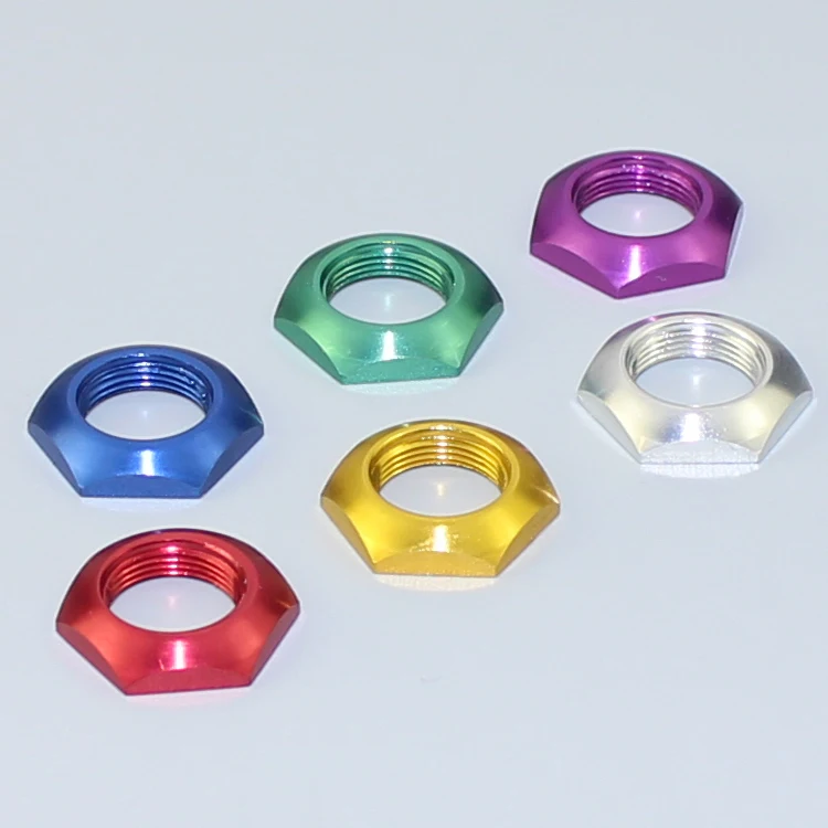
Nope, it was the anodized type but also from LMS....I was going to gamble on a six-pack of these, but never did;

 
Back
Top