Such a Kliché...... :-)

droneshotfpv

Active member
I have built a few Klon circuits, from supposed point to point replicas, to "inspired by, and mostly true to original" types. It was probably one of my first actual builds when I made the decision to start building my own FX. They all sound good in their own right, and I treat them as just another OD for certain applications...
Fast forward to my love affair with PedalPCB and everything in it (from products to members and knowledge) I decided to add yet another Klone to my repertoire, so I ordered the Kliché.

As I posted before, I am not well versed in electronics (yet) and "how it ALL works", but I am learning daily to unfold the mystery of the circuits and what makes them tick, or puff up in smoke.... lol

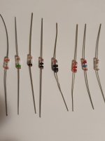
I wanted to ask those with experience in this realm a few questions, if I may. If I am remembering properly, the OG Klon used GE Diodes, the magical and mysterious, as well as ALL belonging to Bill, 1n34a DIODE. Obviously we can get those today, but with all things electronics, the Vf varies. Wasn't the orignals measured, and a conclusion arrived at around 0.39v or 0.40v Vf? I know this isn't really a huge thing to concern myself with, as I have learned over the years that many other factors play a role here, but I was curious about the "tried and true" Vf on the Grand Daddy OG. The reason I am asking this specific question is I got ahold of some OG NOS 1n34a's, (as well as D9E's which I have seen some of you use, and some others that are equivalent to 1n34a) and I wanted to verify their Vf vs. the OG. If I am not mistaken, a few sets of my NOS 1n34a's are reading exactly as the 0.37v - 0.43v Vf, and I will measure again, but 4 or 6 of them are around 0.44v or so.
I am curious about this info because I plan to do something I haven't before, and that is socket the DIODES and run a serious of tests based on the 1n34a and a few others I plan on testing with this circuit, which brings me to the next questions.

When it comes to socketing, is there any noticeable degradation in audio quality when socketed? I know as a general rule, and the applications for other projects I use (unrelated to audio, but IT work, etc) that socketing, or introducing any potential resistance or potential failure point can degrade your signal / quality until the socket is eliminated and whatever you choose is affixed permanently. So is this anything to worry about in the audio realm, or not?

I do plan to do as I have done before, and try my setup with the 1044 vs. 7660S Charge pump, but that isn't anything I am concerned with. the 7660S never seems to squeal for me, which is a plus! lol

Thanks in advance guys, I really appreciate this forum and everyone in it, and I am sorry in advance for the book, I tend to post long winded things... I just like to be thorough. :cool:
 
The Klon is designed in such a way that it's going to work well with just about any diodes you throw at it. You might hear very subtle differences if you're A/B testing with two identical units and only using different Ge diodes.
I understand what you're asking for is a reliable way to test didoes so you can reproduce exactly what Bill did, but there's no such data publicly available on the internet. And anyhow, it wouldn't really matter anyway because, like I said, the circuit design doesn't depend on diode characteristics. It's a wild goose chase.

I'd say go ahead and socket the diodes and test what you have in there to find your favorite. Once, you've decided, use some hot glue to hold them in permanently or remove the sockets and solder the diodes directly to the board. Sockets are good for testing, but with repeated stomping, the parts can work loose.

Also, in my experience, I can replace Ge diodes in any application with BAT46 silicon diodes and can hardly tell any difference in a blind test.
Thanks for the reply! I apologize, I should have mentioned I was being sarcastic about the "magical and mysterious" 1n34a's Bill used. My personal feeling on that was he tried to secure the fact that his was the only way to produce that sound, but I firmly believe it's easily reproduced with equivalent items , and not necessary to get it exactly correct. I was more curious what the circuit used as far as a common Vf, mostly for reference sake. I was going to run a few tests with what I have (the NOS variants) vs some other diodes and LED's etc, and record my results to listen back to them. I basically want this to be my demonstration platform for a range.of diodes and show that minimal differences.

I've never socketed anything aside of IC's before, so I wasn't sure how "well" it worked for things like diodes, but I assumed as you said, that repeated use might cause issues / secure problems, so I appreciate info on that also. I may start socketing things like DIODES and Transistors, etc. I gotta learn somehow, right? hahahatha Thanks again for your response!
 
The forward voltage measured in the original trace by soulsonic was approx 0.35v. He either used a dca75 or 55 I genuinely don't remember which now. A dca75 diode test runs at 1.5ma whereas my multimeter runs at 0.5ma so the figures I get are way off this. I could never work out why I was unable to find any germaniums that tested in the 0.35 range so sent him a message on freestompboxes and asked him which is why I know he used a peak atlas (most germanium diodes are in the 0.23 - 0.30 range on my multimeter)

When I disappeared down my own klon rabbithole I borrowed a dca75 from a friend to go through my own stash. I also put a pair of each type of germanium I had on a breadboard and ran jumper wires to sockets in my klon so I could really quickly switch between them. I tested

NOS TFK 1n34a - sounded pretty harsh I have about 20 of these and have broken about 5, the glass is really fragile.
Modern tayda 1n34a bought in 2013ish - pretty fuzzy sounding
NOS green band 1n34a - very nice clippers in every circuit I've tried them in
NOS hitachi 1n60 - my favourites in a klon circuit. I only bought 10 of these and wish I'd bought more.
D9e - sounds great in a klon
D9b - sounded just like d9e
D9k - these are pretty special they have a very soft compression that's different to any other germaniums I have. They don't sound 'right' in a klon if you're after accuracy but they do sound good.

As Jubal said the differences are very subtle and if you run your gain low you won't even be hearing the diodes anyway. I'd quite happily use any of my stash which measure in the correct range apart from the TFKs and the ones I got from Tayda (I did the heat test on those and they're definitely germanium not silicon workalikes).
 
Last edited:
The forward voltage measured in the original trace by soulsonic was approx 0.35v. He either used a dca75 or 55 I genuinely don't remember which now. A dca75 diode test runs at 5ma whereas my multimeter runs at 1.5ma so the figures I get are way off this. I could never work out why I was unable to find any germaniums that tested in the 0.35 range so sent him a message on freestompboxes and asked him which is why I know he used a peak atlas (most germanium diodes are in the 0.23 - 0.30 range on my multimeter)

When I disappeared down my own klon rabbithole I borrowed a dca75 from a friend to go through my own stash. I also put a pair of each type of germanium I had on a breadboard and ran jumper wires to sockets in my klon so I could really quickly switch between them. I tested

NOS TFK 1n34a - sounded pretty harsh I have about 20 of these and have broken about 5, the glass is really fragile.
Modern tayda 1n34a bought in 2013ish - pretty fuzzy sounding
NOS green band 1n34a - very nice clippers in every circuit I've tried them in
NOS hitachi 1n60 - my favourites in a klon circuit. I only bought 10 of these and wish I'd bought more.
D9e - sounds great in a klon
D9b - sounded just like d9e
D9k - these are pretty special they have a very soft compression that's different to any other germaniums I have. They don't sound 'right' in a klon if you're after accuracy but they do sound good.

As Jubal said the differences are very subtle and if you run your gain low you won't even be hearing the diodes anyway. I'd quite happily use any of my stash which measure in the correct range apart from the TFKs and the ones I got from Tayda (I did the heat test on those and they're definitely germanium not silicon workalikes).

More great info, I appreciate the time to post this information! As far as using my Klon builds, I always run my gain at around 2:00 or 3:00, to make sure I am getting that DIODE sound pumping. Personally, and I know everyone is different, I have never had a desire to run it low gain / clean boost land, but again, that's just me.

I did not know about the DCA75 @5ma, and I am not sure what mine does, but it's a cheaper DMM, so I can only assume it doesn't output the 5ma.. How would I go about testing / figuring that out?
I have noticed as well that my D9E's have been great diodes in pretty much everything I have put them in, so it's good to know it's not just me. :)

I'm not really looking to go "all OG spec" for the Klon, but more using this build as a testing platform. I am the IT Director for a school of students with complex learning disabilities, but I also teach a technology class for those interested in electronics, IT, and music. They have shown a real interest in Audio circuits. Some of them have had that question about "what makes the sounds the way we hear them", and of course have done deep YouTube dives on their own. I wanted to use this fabled circuit, and be able to swap out diodes, and other components to show them that the diodes, while definitely contributing to part of the sound, aren't the end all be all "definer", and how just swapping DIODES might change it a little, but there is more to it than just that.
I am going to socket the DIODES, some key resistors and caps, and demonstrate how those affect the sound as much as, if not more than the DIODES alone. I figured using this particular circuit would be good as well, because it's a "fabled and mysterious" circuit. lol

I truly appreciate all the replies!
 
one note about using sockets -- when you find the diode you want to use in a socketed pedal you can also solder the diode into the socket. you might find than just soldering in the middle leg will be enough to keep it in place and still permit easy removal. but no problem doing that to all three legs. no need to go through the extra step to remove the socket pins.
 
The forward voltage measured in the original trace by soulsonic was approx 0.35v. He either used a dca75 or 55 I genuinely don't remember which now. A dca75 diode test runs at 5ma whereas my multimeter runs at 1.5ma so the figures I get are way off this. I could never work out why I was unable to find any germaniums that tested in the 0.35 range so sent him a message on freestompboxes and asked him which is why I know he used a peak atlas (most germanium diodes are in the 0.23 - 0.30 range on my multimeter)

When I disappeared down my own klon rabbithole I borrowed a dca75 from a friend to go through my own stash. I also put a pair of each type of germanium I had on a breadboard and ran jumper wires to sockets in my klon so I could really quickly switch between them. I tested

NOS TFK 1n34a - sounded pretty harsh I have about 20 of these and have broken about 5, the glass is really fragile.
Modern tayda 1n34a bought in 2013ish - pretty fuzzy sounding
NOS green band 1n34a - very nice clippers in every circuit I've tried them in
NOS hitachi 1n60 - my favourites in a klon circuit. I only bought 10 of these and wish I'd bought more.
D9e - sounds great in a klon
D9b - sounded just like d9e
D9k - these are pretty special they have a very soft compression that's different to any other germaniums I have. They don't sound 'right' in a klon if you're after accuracy but they do sound good.

As Jubal said the differences are very subtle and if you run your gain low you won't even be hearing the diodes anyway. I'd quite happily use any of my stash which measure in the correct range apart from the TFKs and the ones I got from Tayda (I did the heat test on those and they're definitely germanium not silicon workalikes).
What do you like about the 1n60 and the D9e?
 
What do you like about the 1n60 and the D9e?

I like the way they breakup when they clip it's very even without being too bass heavy. It's actually pretty hard to describe why I liked them without falling into the usual overused guitarist terms tbh.

The differences between most of my germanium diode stash are pretty subtle and can be dialled out by adjusting the gain/treble knob, however, there are definite differences and there is a lot more going on than just forward voltage.

When I breadboarded them all the standouts for clipping in a way I found pleasing were the 1n60 (I've used some black band 1n60s before and they were much darker/bass heavy), d9e's and I suppose the d9b as they sounded pretty much the same. Also the green band 1n34a have a very quick attack and are pretty clear even when the gain is pretty high.

As I said in a previous post the other NOS 1n34a with a black band I tried were quick harsh in comparison and the tayda 1n34a were very fuzzy/fizzy sounding.

I've attached a picture of my current stash below from L-R is 1n60, green band 1n34a, TFK 1n34a, Tayda 1n34a, some weird germanium which I don't remember buying and just found in a bag when I was getting the others out, d9b, d9e and d9k.
 

Attachments

  • 20210622_012859.jpg
    20210622_012859.jpg
    837.6 KB · Views: 36
Last edited:
I like the way they breakup when they clip it's very even without being too bass heavy. It's actually pretty hard to describe why I liked them without falling into the usual overused guitarist terms tbh.

The differences between most of my germanium diode stash are pretty subtle and can be dialled out by adjusting the gain/treble knob, however, there are definite differences and there is a lot more going on than just forward voltage.

When I breadboarded them all the standouts for clipping in a way I found pleasing were the 1n60 (I've used some black band 1n60s before and they were much darker/bass heavy), d9e's and I suppose the d9b as they sounded pretty much the same. Also the green band 1n34a have a very quick attack and are pretty clear even when the gain is pretty high.

As I said in a previous post the other NOS 1n34a with a black band I tried were quick harsh in comparison and the tayda 1n34a were very fuzzy/fizzy sounding.

I've attached a picture of my current stash below from L-R is 1n60, green band 1n34a, TFK 1n34a, Tayda 1n34a, some weird germanium which I don't remember buying and just found in a bag when I was getting the others out, d9b, d9e and d9k.
Wondering if you might be interested in trying an experiment.
Thing would be to use a DMM set to resistance measurement and see what it reads when you put the red probe on the cathode and black lead on the anode of those Ge diodes.
My guess is the ones that sound darker and more aggressive have a higher resistance measurement. The ones with more 'clarity' will be lower resistance.
Sure no problem. Do I need to have them in a circuit or just measure them in isolation? I can do it tonight and report back.
 
Ok @jubal81 now I'm officially fooking intrigued. I'm working from home and had a few mins between meetings so grabbed a few diodes to test this. Numbers have forward voltage followed by resistance. I tested one of each but multiple for a few that were weird

Hitachi 1n60 - 0.262/95.4k
TFK 1n34a - 0.263/cycles between 9.2k and UL
0.261/308k
Green 1n34a - 0.277/12.7k and UL
0.245/256k
0.248/11.5k and UL
Tayda 1n34a - 0.245/203k
Mystery germ - 0.245/973k
0.243/1.68M
D9B. - 0.238/9.1k and UL
D9E. - 0.255/159k
D9K. - 0.233/10k and UL

Now what does that actually mean? I have no idea but I'm fascinated enough to set up my breadboard and test these again when I'm free. Anything low seems to cycle rapidly between a value around 10k and open circuit. Those mystery diodes which I don't remember buying are MUCH higher than the others. I also applied the diode test in the opposite direction and none of them are passing current the wrong way.

I'd love to know what this means. It had never occurred to me to measure the resistance of diodes. When I get a chance I'll breadboard them with a klone test them all and record some audio with a combination of high and low resistance to see if I can hear a difference. I'll upload the audio files here if there's any interest?
 
Sorry, I should have told you before you should set the range on your DMM to 6M manual. That will solve that issues where the numbers are jumping around.
 
  • Like
Reactions: fig
I like the way they breakup when they clip it's very even without being too bass heavy. It's actually pretty hard to describe why I liked them without falling into the usual overused guitarist terms tbh.

The differences between most of my germanium diode stash are pretty subtle and can be dialled out by adjusting the gain/treble knob, however, there are definite differences and there is a lot more going on than just forward voltage.

When I breadboarded them all the standouts for clipping in a way I found pleasing were the 1n60 (I've used some black band 1n60s before and they were much darker/bass heavy), d9e's and I suppose the d9b as they sounded pretty much the same. Also the green band 1n34a have a very quick attack and are pretty clear even when the gain is pretty high.

As I said in a previous post the other NOS 1n34a with a black band I tried were quick harsh in comparison and the tayda 1n34a were very fuzzy/fizzy sounding.

I've attached a picture of my current stash below from L-R is 1n60, green band 1n34a, TFK 1n34a, Tayda 1n34a, some weird germanium which I don't remember buying and just found in a bag when I was getting the others out, d9b, d9e and d9k.
I believe the green band 1n34a is the Japanese Unizon 1n34a.
 
Ok @jubal81 now I'm officially fooking intrigued. I'm working from home and had a few mins between meetings so grabbed a few diodes to test this. Numbers have forward voltage followed by resistance. I tested one of each but multiple for a few that were weird

Hitachi 1n60 - 0.262/95.4k
TFK 1n34a - 0.263/cycles between 9.2k and UL
0.261/308k
Green 1n34a - 0.277/12.7k and UL
0.245/256k
0.248/11.5k and UL
Tayda 1n34a - 0.245/203k
Mystery germ - 0.245/973k
0.243/1.68M
D9B. - 0.238/9.1k and UL
D9E. - 0.255/159k
D9K. - 0.233/10k and UL

Now what does that actually mean? I have no idea but I'm fascinated enough to set up my breadboard and test these again when I'm free. Anything low seems to cycle rapidly between a value around 10k and open circuit. Those mystery diodes which I don't remember buying are MUCH higher than the others. I also applied the diode test in the opposite direction and none of them are passing current the wrong way.

I'd love to know what this means. It had never occurred to me to measure the resistance of diodes. When I get a chance I'll breadboard them with a klone test them all and record some audio with a combination of high and low resistance to see if I can hear a difference. I'll upload the audio files here if there's any interest?
What make and model DMM are you using?
 
Fluke 83V.

You can also test them with those famously cheap (and pretty good) MEGA328 component testers. The Ir measurement is the reverse leakage.
I meant to buy one of those before I had my hiatus from building for a few years. I might pick one up before I test these again. It'll be next week probably before I have time to sit down and go through them properly anyway - I've got a big project from work on at the minute.
 
Inspired me to do some auditions today and I’ve got a new favorite Klon pair: the green band sold to me as 1N34.
FV on my Fluke is .35 and leaky as hell. Less aggressive and more clarity.
The labeled 1N34 I have look just like Bills diodes and measure .35 fv, but are less leaky. These sounded darker and more compressed.
 
Back
Top