
You are using an out of date browser. It may not display this or other websites correctly.
You should upgrade or use an alternative browser.
You should upgrade or use an alternative browser.
Tayda Drill for AionFX?
- Thread starter joelorigo
- Start date
mkstewartesq
Well-known member
You can always check with the guy from Aion but I suspect that you are going to need to just enter coordinates manually (that’s what I do with Aion PCBs - use a small ruler and measure out the drilling template that he provides in his documentation and then use it to create a template.)Is there an easy way to use the Tayda drilling service for a Aion FX pedal? Is the only way to do it is to start with a blank template and enter a drilling point for every hole?
You never know – but he seems kind of down on Tayda and doesn’t use them for his own enclosures so I’m not sure that he would just keep Tayda drilling templates on hand. But again, might be worth asking him.
Mike
mkstewartesq
Well-known member
Also, there is a subforum here under Toolbox where you can request drilling templates that others have made. Maybe request what you are looking for there. I’ve done one for the Azure chorus pedal if you need that one.
Mike
Mike
joelorigo
Well-known member
Thank you, I will do that! I'm looking for one for the Tempest btw.Also, there is a subforum here under Toolbox where you can request drilling templates that others have made. Maybe request what you are looking for there. I’ve done one for the Azure chorus pedal if you need that one.
Mike
joelorigo
Well-known member
Thanks, I'm looking for one for the Tempest. When you say "put them into the tool" you mean enter coordinates manually, correct?The AionFX drilling templates are really good - all you have to do is convert them into millimeters and put them into the tool.
That being said, I've got several templates I could share if you let me know which one(s) you need.
mkstewartesq
Well-known member
Yes, that is what you would need to do. I believe he provides the sizes for the holes in inches (hence the comment that you would need to convert them to millimeters) but that’s not the same as actually creating the coordinates for where the holes go. For that, I use a ruler.Thanks, I'm looking for one for the Tempest. When you say "put them into the tool" you mean enter coordinates manually, correct?
You can basically assume that the pedal face is centered so I basically measure between two holes on the same row, then from holes on an upper row to a lower row just to double check and go from there. For example, if there are two knobs on the top row and they measure at 22 mm apart, I would calculate that the X coordinates would be -11 and +11 (if zero is the centerpoint then holes 22 mm apart would be plotted as 11 mm to the left of zero and 11 mm to the right of zero).
M
edit to add – actually, I’m wrong. I’m looking at his template and he does provide X and Y coordinates in inches. So the other poster was correct that you would just convert those to mm. I still use a ruler to be sure but I’m probably doing too much work.
Fingolfen
Well-known member
That's one of the few I don't have... a 7 knob AionFX... that's unusual!Thank you, I will do that! I'm looking for one for the Tempest btw.
Fingolfen
Well-known member
You don't have to measure them... Kevin includes the coordinates on the drill template, so you just need to convert those to mm and run with it... same with the hole diameter...Yes, that is what you would need to do. I believe he provides the sizes for the holes in inches (hence the comment that you would need to convert them to millimeters) but that’s not the same as actually creating the coordinates for where the holes go. For that, I use a ruler.
You can basically assume that the pedal face is centered so I basically measure between two holes on the same row, then from holes on an upper row to a lower row just to double check and go from there. For example, if there are two knobs on the top row and they measure at 22 mm apart, I would calculate that the X coordinates would be -11 and +11 (if zero is the centerpoint then holes 22 mm apart would be plotted as 11 mm to the left of zero and 11 mm to the right of zero).
M
Last edited:
mkstewartesq
Well-known member
Yes, I realized I was wrong once I looked at the template that I have and I edited my post above I guess around the same time you were replying. Sorry for the originally inaccurate information.You don't have to measure them... Kevin includes the coordinates on the drill template, so you just need to convert those to mm and run with it... same with the hold diameter...
Silver Blues
Well-known member
Yep!Is the bottom number on the Aion drill template the size of the hole?
mkstewartesq
Well-known member
Oh, trust me, you don’t know the meaning of the word “tedious” until you try to take two different drill templates - one 1590BB and one 125B-from two different manufacturers with different sized boards and different knobs spacing and calculate how they would work in a two and one build in a different sized enclosure. I’m still white-knuckling it for when this enclosure eventually comes in as to whether or not I actually got everything rightI guess I could give doing it manually a try. I’m just worried I might screw something up and have a wrongly drilled enclosure. And it seems tedious

(This will be the Mad Bean Current Lover o the left and the PedalPCB XC Phase on the right in a 1590DD.)

joelorigo
Well-known member
I'm on the Tayda drill page creating a template manually. I've got all the "Face" holes plotted, so far not as taxing as I assumed ")
I am going to order the gold enclosure from them so I need to add .2mm to all the diameter entries, correct?
And, to plot the holes for the jacks and DC jack on the "Top," am I still to use the center point for the x & y position entries?
I am going to order the gold enclosure from them so I need to add .2mm to all the diameter entries, correct?
And, to plot the holes for the jacks and DC jack on the "Top," am I still to use the center point for the x & y position entries?
mkstewartesq
Well-known member
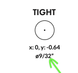
1. Yes, add 0.2 mm to all hole measurements. In fact, you might want to make it 0.3 or 0.4 because I have gotten print jobs back where the powder coating was thicker than expected and I ended up having to use a reamer to make the hardware fit even though it should have fit with just the 0.2 mm adjustment. That extra 0.1 mm or 0.2 mm isn’t going to be visible once you put the hardware in.I'm on the Tayda drill page creating a template manually. I've got all the "Face" holes plotted, so far not as taxing as I assumed
I am going to order the gold enclosure from them so I need to add .2mm to all the diameter entries, correct?
And, to plot the holes for the jacks and DC jack on the "Top," am I still to use the center point for the x & y position entries?
2. Let me look at my templates and double check on your second question. For some reason, I seem to remember the axis being a little different on those. I’ll be right back in a bit.
M
joelorigo
Well-known member
Yes, I tried measuring from the center point and that's not it. It seems like the "Top" is from it's on center point maybe? Of which there is no center point on the top of the drip template marked.
Also, once all the holes are plotted, is there a way print at 100% size to double check against the Aion drill template?
Also, once all the holes are plotted, is there a way print at 100% size to double check against the Aion drill template?
mkstewartesq
Well-known member
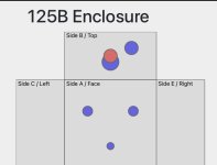
For your second question, the top side (B) is also divided into four quadrants (which I think you already understood, but I just wanted to be clear). See my picture below where the red circle is exactly at X equals zero and Y equals zero. So if you wanted to move the hole more toward the top of the enclosure from the dead center of side B, the Y would be a negative number and if you wanted to move it closer to the bottom of the enclosure from the center of side B, Y would be a positive number.I'm on the Tayda drill page creating a template manually. I've got all the "Face" holes plotted, so far not as taxing as I assumed
I am going to order the gold enclosure from them so I need to add .2mm to all the diameter entries, correct?
And, to plot the holes for the jacks and DC jack on the "Top," am I still to use the center point for the x & y position entries?
Attachments
Similar threads
- Replies
- 2
- Views
- 310
- Replies
- 3
- Views
- 461
- Replies
- 2
- Views
- 442