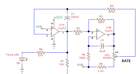
This Week on the Breadboard: Phase 90

I really need to get this one breadboarded, but I was looking at the schematic and comparing it to the vanilla Phase 90, and noticed something.

Tracing from the audio signal in through to IC1A - it's going into pin 2 (-) on this schematic, but on the standard Phase 90 it goes into pin 3 (+)... granted, going through all of the ICs both the "A" and "B" pin attachments seem to be similarly reversed. Was this intentional?
 
My money's on Cooder.
Well I think we all win then...
While I originally thought my build report might be in January 2024 or 2025 it turns out somewhere in the golden middle...
Here's the "Phases of the Moon", sounds and works excellent and the footswitch juuuust fitted in there, geeeez it's a bit tight, she said, but fun and all worth it ;)
Great soundz and variety, love having a Depth control and the Colour has great shades of phaseygoodiness.
Great circuit work and Chuck held my hand getting the J113 jfets to work in there and what to watch for when selecting a quad with the fab jfet tester from here:
https://forum.pedalpcb.com/threads/why-are-jfets-such-a-pain-in-the-ass.4878/post-219671
(note: there's a wee mistake in the schematic of that tester, I can post an update if someone wants it, easy enough to spot anyway).
So it's great to know that we can get this working with still readily available in production jfets. I tested about 80 pieces of J113 sourced from Mouser and found a bunch of tightly matched quads.

Anyway, enough fluffing around, here's the swirly goods:

xxf9vtv.jpg


pPjtMWj.jpg


soIoAqw.jpg


QKNuX0P.jpg


uxf4ijT.jpg


qbTXQmA.jpg
 
Last edited:
could you clarify what the COLOUR (appreciate the non-americanized spelling on that one btw) control does? it seems like it replaced the RANGE trimmer, which from the name makes me think it shifts the sweep toward the treble or bass end? am i right?
 
and another question: as i understand it it's standard best practice so isolate the power supply for the LFO from the rest of the circuit so as to avoid crossover "tick", and yet in the phase 90 and PH-1R that isn't the case, nor have you felt the need to do so in your pretty extensive redesign of the circuit. is it that the single-op-amp LFO doesn't produce a tick, or is there another reason why that isn't a concern here?
 
could you clarify what the COLOUR (appreciate the non-americanized spelling on that one btw) control does? it seems like it replaced the RANGE trimmer, which from the name makes me think it shifts the sweep toward the treble or bass end? am i right?
You are correct.

and another question: as i understand it it's standard best practice so isolate the power supply for the LFO from the rest of the circuit so as to avoid crossover "tick", and yet in the phase 90 and PH-1R that isn't the case, nor have you felt the need to do so in your pretty extensive redesign of the circuit. is it that the single-op-amp LFO doesn't produce a tick, or is there another reason why that isn't a concern here?
There are degrees of isolation from putting the LFO in one corner of the board to creating separate power and ground planes for the LFO. We seem to be getting away with doing the minimum. IC3B is a Schmitt Trigger, which normally switches rapidly between OFF & ON. That rapid switching can introduce current spikes into the power and ground traces and those current spikes can produce ticking in the audio portions of the circuit. C7 and R23 slow down the switching so there is less noise produced by the LFO. There are three ways to combat noise in a circuit: reduce the source of unwanted noise, reduce the susceptibility to noise, and reduce the coupling. The designers of the Phase 90 chose door #1 and it was sufficiently effective that no other measures were required. Since the LFO and the 3rd phase-shifter stage share the same IC package, we have basically no isolation. The susceptibility of this circuit is low because the gain is unity throughout. It would take a pretty big disturbance to be audible.

There is a concept in engineering know as "good enough." This circuit is good enough and adding more parts, making it a 4-layer board, etc. would cost more without making the performance noticeably better.
 
Last edited:
since the "throb" LED takes its input as pin 7, the square wave output of the op amp. am i correct in assuming that it will only blink in time with the rate and not ramp up and down like the triangle wave output of the LFO? because if so i think i have something valuable to contribute and not just asking questions
 
did you end up doing the PH-1? i'm working on the PH-1R right now and would love to hear your insights
I did not. They are so similar that I didn't see the point. I will say that the PH-1r has less distortion than the PH-1 due to the linearizing resistors around the JFETs.

since the "throb" LED takes its input as pin 7, the square wave output of the op amp. am i correct in assuming that it will only blink in time with the rate and not ramp up and down like the triangle wave output of the LFO? because if so i think i have something valuable to contribute and not just asking questions
The Rate LED blinks on & off at the LFO rate, does not ramp. What is your idea?
 
so this is a nut i've been trying to crack for a while.
almost every approach i've seen published has taken the signal from pin 7 -- the square wave output of the op amp -- as their starting point. some use a capacitor to smooth it out but the problem with that is that the capacitor's value is fixed and thus so is the speed of the ramp, so while it may be just right in the middle, it will be too slow for fast LFO speeds and too fast for slow LFO speeds.

to get a satisfying ramp that reflects the true shape of the LFO the LED current needs to be taken from the LFO output itself.
the best implementation i've seen of it in action is here:


but they don't provide schematics since these are mods they're offering for sale -- trade secrets i presume, though i haven't reached out to ask if they'd be willing to share.

the best implementation i've seen with a schematic attached is here:
with the circuit posted here:

this person took the output of the LFO before the 3.9M resistor, cancelled the DC bias using a large cap and resistor combo and then drove the LED with an op-amp configured as a current driver. and it looks pretty damn good, but there's still a little room for improvement -- because the DC bias is cancelled completely, half of the waveform is below zero and thus clipped, and so the LED spends half its time completely off. my ideal would be to have the LED only hit zero at the bottom of the wave, so it seems like the answer is trickling in a little bias current from the reference voltage. it only needs a little bit so a very large (~15M) resistor is in order. this is working really well for me, at least in simulation. one possible remaining tiny issue is that the faster waveforms are higher in amplitude than the slow ones, but if you dial it in for the slowest one, having faster ones clip a little at zero and overshoot maximum brightness by 2mA at the peaks doesn't seem like a big problem. here's the simulation, let me know what you think:

 
Last edited:
Have you built it yet?

If I was going to add a 2nd opamp, I'd construct a 2 opamp LFO like this one. This is purely an example; all component values are negotiable. The triangle output is taken from U1-1. Rates below 0.1Hz are attainable.

1754670429999.png
 
i haven't built it yet, i'm away at a cabin right now which gives me lots of time for theoretical circuit building but no ability to build practical ones.

doing it as a 2-op amp true-triangle LFO makes sense. i've heard people say that the slightly exponential "shark fin" shape of the single-op amp LFO is part of the signature sound of the phase 90 but i doubt anybody can actually tell. as discussed above though it does soften the square wave of the schmitt trigger, which greatly simplifies the power section.
 
Last edited:
Back
Top