Chuck D. Bones
Circuit Wizard
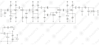
As part of a larger project, I simulated and breadboarded the Windmill Hi-Watt amp-in-a-box. The Windmill schematic is reprinted below. I don't like MOSFETs for the first stage because they can be noisy. I changed Q1 to a BF244B JFET (J112 also works). R1 now returns to GND. I reduced R2 to 1.5K to get the bias right and reduced R4 to 470Ω to get the gain right. C3 is overkill at 100μF, so I reduced it to 10μF. C7 & C14 are also oversized; I reduced them to 1μF. Likewise, C12 was reduced to 47nF. The stock values work fine, but it's a bit silly to me for coupling caps to roll-off below 1Hz. D2 & D3 are unnecessary, so they're gone. The original Vref biases the MOSFETs to clip very asymmetrically. I installed a 10K trimpot between R101 & R102. I changed R101 & R102 to 10K. I dialed the bias in for nearly symmetric clipping. Q2-D & Q3-D are about 5.9V. Then I took a look at the feedback network comprised of C17 & R18. Putting a feedback loop around a tone stack is nothing new; Fender & Marshall have done it for decades. but in this circuit, the feedback is so strong that it effectively cancels out the effects of the tone stack. I increased R18 to 470K to reduce the feedback and put a toggle switch in series to kill the feedback altogether if I want.

The LTSpice freq response plot below shows the effect of the feedback. GAIN, TREBLE & BASS at noon, signal measured at Q3-D. Green trace: R18 = 200K. Blue trace: R18 = 470K, Red trace: no feedback (R18 removed). As you can see, the feedback lowers the gain and flattens the freq response. The feedback also reduces the distortion, but why would we want to do that?

for moderate GAIN settings, the tone is clear & clean. Turn the gain up and dig the pick in and we get a nice growl with a smooth decay. With the feedback disabled, the gain is a little higher, the tone controls are more effective and there is still plenty of clean headroom.
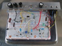
Knobs (L-R): MASTER, BASS, TREBLE, GAIN. The toggle switch kills the feedback.
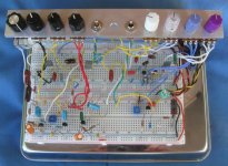
Q1 on the lower right, Q2 in the middle, Q3 on the lower left. All three FETs run at about 1mA drain current.


The LTSpice freq response plot below shows the effect of the feedback. GAIN, TREBLE & BASS at noon, signal measured at Q3-D. Green trace: R18 = 200K. Blue trace: R18 = 470K, Red trace: no feedback (R18 removed). As you can see, the feedback lowers the gain and flattens the freq response. The feedback also reduces the distortion, but why would we want to do that?

for moderate GAIN settings, the tone is clear & clean. Turn the gain up and dig the pick in and we get a nice growl with a smooth decay. With the feedback disabled, the gain is a little higher, the tone controls are more effective and there is still plenty of clean headroom.
Knobs (L-R): MASTER, BASS, TREBLE, GAIN. The toggle switch kills the feedback.
Q1 on the lower right, Q2 in the middle, Q3 on the lower left. All three FETs run at about 1mA drain current.


