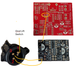
TPA3118 60W Power Amp Module

There's really nothing to design. The circuit is right out of the TPA3118 datasheet. So it's just a clone of the boards we've been buying but using thru-hole components. Only did it because... Why not?

And I have a very cheap hot plate that gets too hot, so need to work fast.

FYI, a close up of the result. Just did 9 more boards all at once. This wasn't hard at all, but absolutely need a USB microscope to see the pins close up while the the solder is melted and getting it lined up. I used a toothpick to put a very little bit of solder paste along the pins and on the heat sink pad on the PCB and on the pad on the bottom of the IC. When the solder paste melts it wicks onto the pads and is ready for the IC. Then some pointy tweezers to place and nudge the IC until perfect. Same tweezers to move the board carefully up off the hot plate. After they cooled, used a tooth pick to buff off any tiny solder balls stuck around the pins.
View attachment 62124
By the way, I'm willing to sell some of these, too, but it's kinda pointless with the real ones still available for cheap. I've already soldered the 3118 on all 10 of them. I would have to sell each for $6 as they are (no other components), which is already the same price the real ones. So, this would only be for folks that really want to build the whole deal themselves (like me). I'm wondering if it's worth designing an all-in-one board with preamp and 3118 but the board-sandwich method works really well and makes great use of space in the 125B.
 
Since the cost of shipping from me to anyone outside north America is more than it would cost direct from PCBWay, I've shared the projects there. At the moment, the Volume-Only boards are showing up but not the others. I think they go through some type of review before going live to everyone.

Of course, I'm happy to sell these for cheap in north America and I can include other parts as well since I have everything. Just doesn't make financial sense to ship international when it's cheaper to buy direct.
 
Last edited:
Minor update to the build doc. I changed all the LED resistors that go to 24V to 100k. 47k is too bright for me. But, you might want different. I suggest testing your LEDs at what ever power supply voltage you choose to make sure the brightness is what you want. I don't like blinding pedal LEDs. Also change the link to the 220uf cap at mouser. The previous link was to a cap that is 1mm tooo tall. The pots are 10mm high from PCB to the case, so all the components on the board must be 10mm tall or less.
 
Added a subfolder with videos of soldering the TPA3118.

Link to the upper level folder:

Description of the process with direct link to the videos...

Videos show the process of soldering a TPA3118 to the board.

First Video is the application of solder paste with a tooth pick to the PCB.
This is using a very tiny amount of no-clean solder paste.
I’m careful not to leave any paste anywhere but where it is supposed to be.
https://drive.google.com/file/d/1lt_ZqyDOzroHl71-aa7eTO1sPOqIvmZi/view?usp=drive_link

Second Video is the application of solder paste with a tooth pick to the bottom of the TPA3118.
This ensures there will be enough solder and some flux on the IC to get a good solder flow.
https://drive.google.com/file/d/1sV1S1fdVRavs7U-p2nuOOFPRRwq1SbFu/view?usp=drive_link

Third Video is flowing the solder and adding the TPA3118.
The hot plate is already up to temperature, about 325 Fahrenheit.
The PCB is laid onto the plate and wait for the solder to all flow and wick onto the pads.
Then the IC is applied with some pointy tweezers and nudged into place.
Then the PCB is carefully removed from the hot plate and set aside to cool.
https://drive.google.com/file/d/1O_xk2ix7Je_61Z00tFmFoQ9teNyKT7G9/view?usp=drive_link

Fourth Video Buffing any little solder remnants with a tooth pick and brushing.
You can see some very tiny beads being knocked off by the tooth pick.
https://drive.google.com/file/d/1FRlDJYWNrmMDcHIsJxUTkVqsknLjimx4/view?usp=drive_link

Final Video is cleaning with 99% IPA.
Clean it all up with IPA and inspect for anything wrong under the microscope.
https://drive.google.com/file/d/18zwHHAlTBkC1kf13lI_0zVwgchezy74N/view?usp=drive_link
 
This question may have been covered, but I'm too lazy to look through all of the pages :ROFLMAO:

I understand needing a boost in front to raise the impedance of the input.

But others have mentioned that the TPA power amps are very clean and simply using a preamp straight in would not sound "right". Is this why the TMB circuit was added?

Is there something else that would work to simulate power amp "coloration"? Or something that generates/emulates negative feedback?

So that if someone wanted to hypothetically use a preamp pedal (Argentum 1212, Boogie Monster, Cobbler, etc) straight into it (going through the boost/buffer of course) they could get the "full" amp sound?

Am I thinking too hard about this?
 
Yep. The amp is clean and takes line-level input. The Volume-only and TMB preamps are straight out of typical guitar amps to provide the needed gain and EQ that would typically be applied to a guitar signal. But, it's still only a power amp. These are not emulating any kind or preamp. They are meant to be at the end of your pedal board chain with a good preamp emulation pedal along the way. I happen to really like the AMT legend series 2 pedals as my primary preamp. They switch between a fender clean and many different choices of dirty channel.
 
I want to build an Frfr cabinet for a multiFx pedal I am getting (Valeton Gp-200lt). I think I might use a stereo board. I have some old studio monitors I may take the speakers out of, I even thought salvaging some car speakers. Any ideas for wiring it up? I guess it seems pretty straightforward.
 
I suggest using some stereo amplifier you already have and test out the scenarios first with the potential speakers and figure out exactly what you like and what you need in a power amp and speaker setup. Then plan out a build...
 
I'm running the circuit from post #161 - the TMB. Is it expected that each half of the opamp clips and introduces significant distortion? Powering mine with 23V+. 1in+ and 2in+ are both at 1/2VCC. I've soldered onto perfboard and breadboarded it. From most of what I understand is that this should be mostly a clean power amp.
 
I'm running the circuit from post #161 - the TMB. Is it expected that each half of the opamp clips and introduces significant distortion? Powering mine with 23V+. 1in+ and 2in+ are both at 1/2VCC. I've soldered onto perfboard and breadboarded it. From most of what I understand is that this should be mostly a clean power amp.
Certainly not. The first op-amp stage has a voltage gain of about 9X to get instrument level up to line level into the EQ, which has a significant attenuation. Should not be anywhere near clipping. What signal level are you feeding in?
 
Testing with just a guitar on the input. It's clean until about 0.5/10 on the TMB volume knob, after that it gets louder and more distorted. I did the perf board first, then breadboard to debug it. Both behave the same way with or without the TPA3118 board attached.

Using my audio probe with a voltage divider to ensure I'm not clipping on the probe/headphone amp.
 
Update, tried another 3118 module., one of the ones with "35v" caps and no mute pad. No problems. It gets a bit of mild clipping when running at very high volumes through my 16ohm speaker. Not really sure what was going on there. Maybe an input gain knob would help to limit some high volume clipping
 
Update, tried another 3118 module., one of the ones with "35v" caps and no mute pad. No problems. It gets a bit of mild clipping when running at very high volumes through my 16ohm speaker. Not really sure what was going on there. Maybe an input gain knob would help to limit some high volume clipping
Something is wrong with your circuit. My guess is at least one of the op amps has the wrong (or missing) feedback resistors to set the gain. It should not have enough gain to do this.
 
Confirmed all 4 feedback resistors match, as well as the feedback loop caps, and their connections to ground. A standard PAF output humbucker will give clean tones up until about noon, after that it starts clipping. I messed with it and changed R1 to a 82K and B250K pot in series, R9 to a B500k and 180K in series. Messing with R9 just lowers volume, 680k works. Knocking R1 to about 250K cleans things up. DM coming for a PCB.
 
By the way, all TPA3118/3116 modules have a pair of resistors that determine the gain of the module. Different manufactures may well choose different values for those. Most use the 32db gain setting.
1707678232501.png
1707678267489.png
 
Back
Top