Paul.Ruby
Well-known member
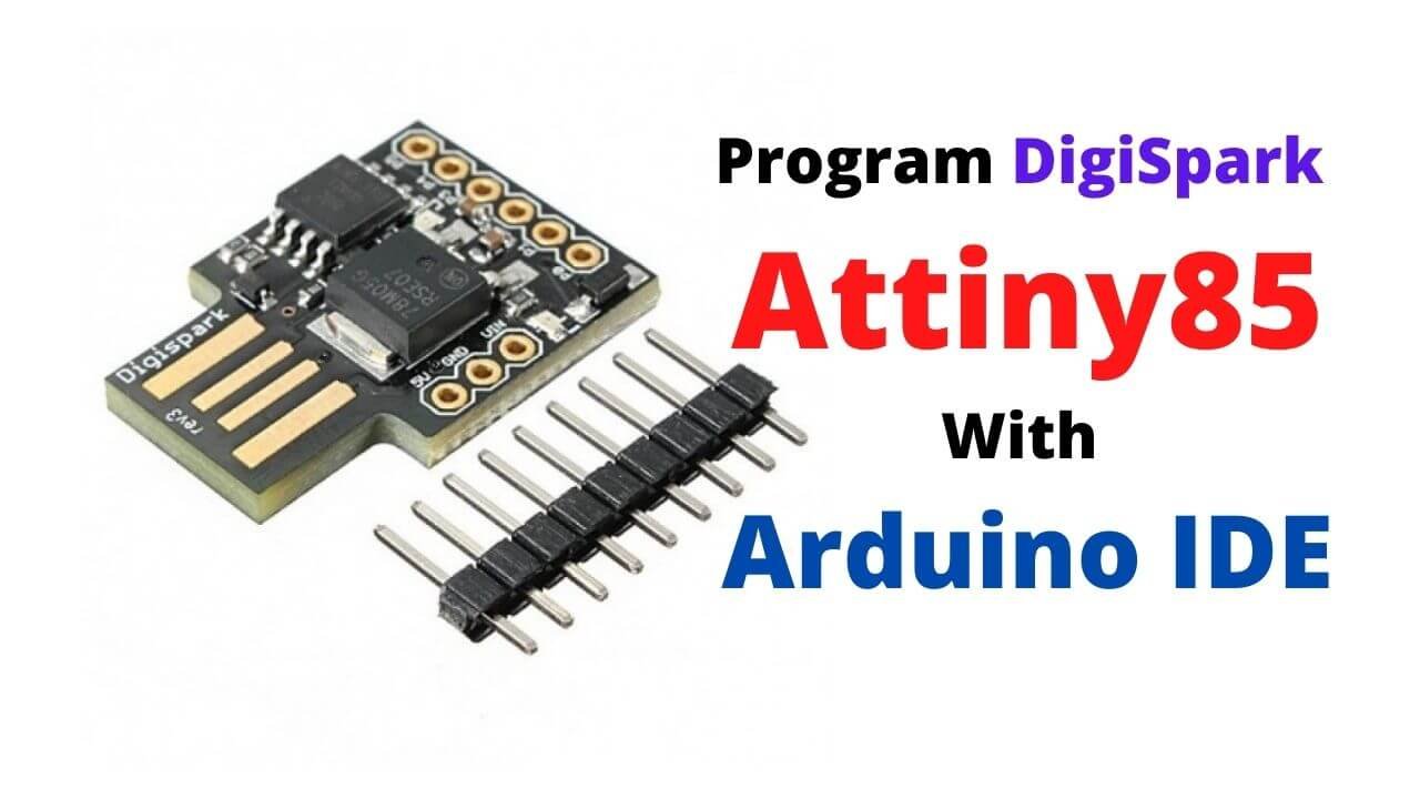
The digispark board is really easy to use and makes this simple and dirt cheap. I have a PCB layout for mounting a digispark in my share drive:
 drive.google.com
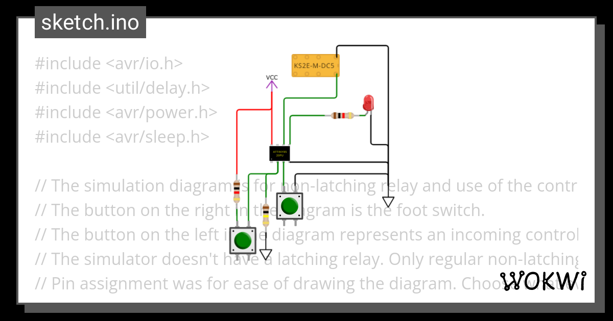
The Arduino sketch file has an option for Digispark boards. Look for these lines and set DIGISPARK true.
The amazon link to clone digispark boards is here:
UPDATE: These boards do NOT have the fuse blown to turn reset into PB5. PB5 is useless.
https://www.amazon.com/dp/B08JGL5TSV?psc=1&ref=ppx_yo2ov_dt_b_product_details
The instructions to use them with Arduino is here:

 iotprojectsideas.com
The digispark is so small, it can mount on the component side. TPA3118 mounts on the copper side. Here's an image of the layout.
EDIT: This reflects changes after learning that PB4 and5 can't be used. PB3 and 4 are toggling during bootloader operation and have circuitry on the board, so can't be used for anything you don't want being toggled for 5 seconds at power-on. PB3 and 4 draw a lot of current when driven high so should not be used for outputs at all. PB3 can be used as the switch input and works fine. PB5 is useless because the digispark clones have not programmed the fuse to make reset into PB5. Uhg. This layout uses PB0,1,2 for LED, Engage and Switch.

PCB - Google Drive
 drive.google.com
The Arduino sketch file has an option for Digispark boards. Look for these lines and set DIGISPARK true.
// Platform for testing if not the final platform.
// Must set this to proper final target before moving the chip off the development platform.
// When all are false, default is the MAS effect switch.
// The sparkfun has an LED on PB0 instead of PB4 on the MAS effect board.
// Digispark On-Board LED is on PB1. Leave Digispark "true" if that is the final target.
#define SPARKFUN_TINY_AVR_PROGRAMMER false
#define DIGISPARK true
The amazon link to clone digispark boards is here:
UPDATE: These boards do NOT have the fuse blown to turn reset into PB5. PB5 is useless.
https://www.amazon.com/dp/B08JGL5TSV?psc=1&ref=ppx_yo2ov_dt_b_product_details
The instructions to use them with Arduino is here:

Program Digispark Attiny85 with Arduino IDE
All about an inexpensive and Compact Alternative to Arduino called ATTINY85 so let's learn to Program Digispark Attiny85 with Arduino IDE.
 iotprojectsideas.com
The digispark is so small, it can mount on the component side. TPA3118 mounts on the copper side. Here's an image of the layout.
EDIT: This reflects changes after learning that PB4 and5 can't be used. PB3 and 4 are toggling during bootloader operation and have circuitry on the board, so can't be used for anything you don't want being toggled for 5 seconds at power-on. PB3 and 4 draw a lot of current when driven high so should not be used for outputs at all. PB3 can be used as the switch input and works fine. PB5 is useless because the digispark clones have not programmed the fuse to make reset into PB5. Uhg. This layout uses PB0,1,2 for LED, Engage and Switch.

Last edited:


