TPA3118 60W Power Amp Module

The digispark board is really easy to use and makes this simple and dirt cheap. I have a PCB layout for mounting a digispark in my share drive:

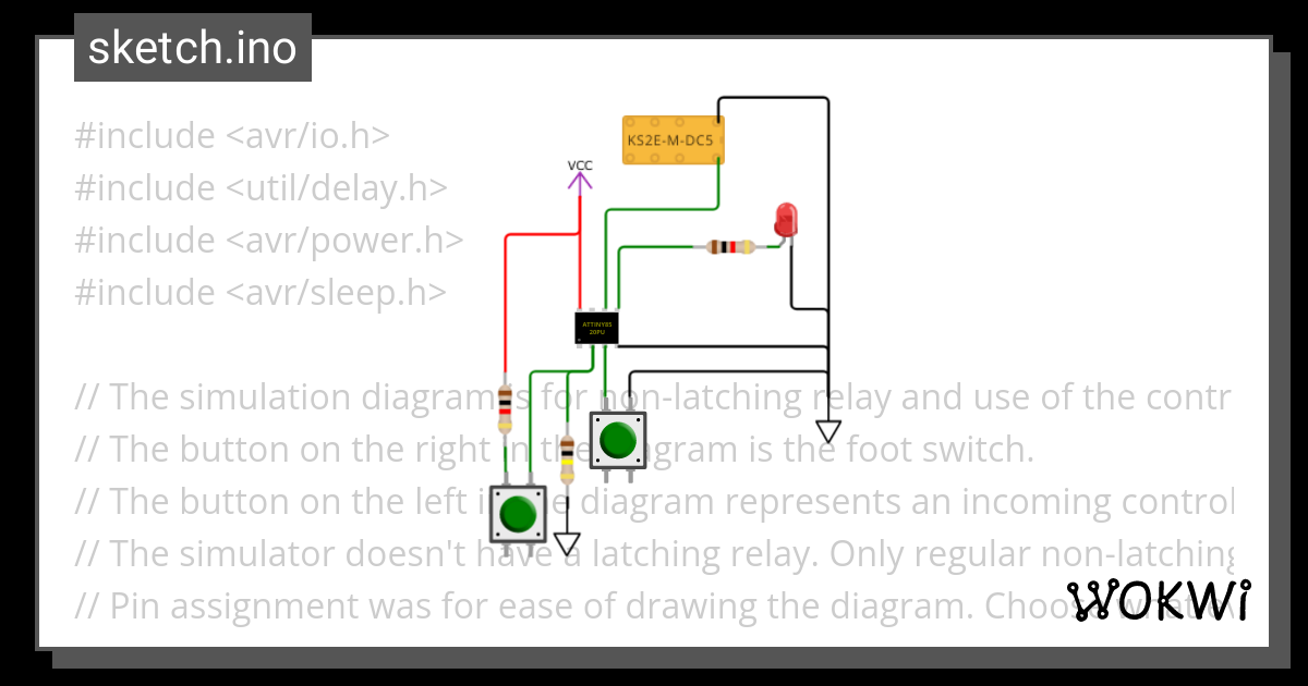
The Arduino sketch file has an option for Digispark boards. Look for these lines and set DIGISPARK true.

// Platform for testing if not the final platform. // Must set this to proper final target before moving the chip off the development platform. // When all are false, default is the MAS effect switch. // The sparkfun has an LED on PB0 instead of PB4 on the MAS effect board. // Digispark On-Board LED is on PB1. Leave Digispark "true" if that is the final target. #define SPARKFUN_TINY_AVR_PROGRAMMER false #define DIGISPARK true

The amazon link to clone digispark boards is here:
UPDATE: These boards do NOT have the fuse blown to turn reset into PB5. PB5 is useless.
https://www.amazon.com/dp/B08JGL5TSV?psc=1&ref=ppx_yo2ov_dt_b_product_details

The instructions to use them with Arduino is here:
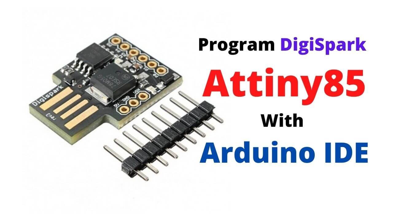
The digispark is so small, it can mount on the component side. TPA3118 mounts on the copper side. Here's an image of the layout.
EDIT: This reflects changes after learning that PB4 and5 can't be used. PB3 and 4 are toggling during bootloader operation and have circuitry on the board, so can't be used for anything you don't want being toggled for 5 seconds at power-on. PB3 and 4 draw a lot of current when driven high so should not be used for outputs at all. PB3 can be used as the switch input and works fine. PB5 is useless because the digispark clones have not programmed the fuse to make reset into PB5. Uhg. This layout uses PB0,1,2 for LED, Engage and Switch.
1697296542062.png
 
Last edited:
Testing the digispark board... Works great.
1697223584417.png
I forgot to shorten the power-on delay to account for the bootloader. In-circuit update of the code!
1697225416237.png
Also measured digispark current draw 1to be 19mA, so will replace the 1k 1W dropping resistor with 680ohm 1/2W. That will keep power dissipation in a 78L05 below 1/8W. This board has a 78M05, which can handle 1W but other versions of the board have a 78L05. The 78M05 doesn't need any dropping resistance at 20mA from a 24V supply but still worth having. 470ohm 1/W would be fine with the 78M05 and a wide range of supply voltage.

EDIT: Current draw went up to 26mA with the resistor changed. Recommend a 470ohm 1/2W dropping resistor. With 23V input, this sends 11V to the regulator, which is fine for a 78L05 or 78M05. If using a 19V main power supply, this will be on the hairy edge of working. Should reduce to 390ohm 1/2W. Maybe a zener would be better to drop the voltage. Don't need to measure current. Just pick a zener to drop your power supply to 10 or 11V into the digispark. And use either 1/2W or 1W zener.

EDIT AGAIN: Changing to zeners. Current is varying too much to trust a resistor. Using two 6.2V zeners in series on mine to drop from 23V to 10V. Changing the PCB layout to allow for 3 zeners in series. Also found the culprit for current draw. The circuitry on PB3 and PB4 for usb will draw quite a bit. Changed the sketch file to configure those as inputs when using digispark. Now current draw is consistently 17mA. Zeners are still a better choice, so leaving them in.

Yet Another EDIT: Running at 1Mhz instead of 16Mhz saves about 8mA, which is important trying to get down from 23V to 5V in the regulator. This is done with the board selection at build time. I was using the default 16.5Mhz. But 1Mhz is still about 1000 times faster than needed for a foot switch. Finding more issues... Sigh... Can't use PB3 or PB4 since those are doing USB things during bootloader. The fuse is not set to change reset into PB5 on these clone boards, so PB5 is useless. PB1 has the on-board LED, which I wanted to avoid turning on and burning 3mA, but only PB0,1,2 are available. PB3 will work as the switch input, but not PB4.

Figured out how to get the clock speed down to 125khz, posted in my sketch file. Current draw is down to 6mA disengaged and 12mA engaged (because of LEDs) which is very easy to handle with just one zener dropping from 23V to 11V.
1697253210469.png
 
Last edited:
Updated the code for ATtiny. It now sleeps waiting for an interrupt on the switch pin. I posted all the supported features of the code over on this thread. This further reduced power draw.
 
Just posted another update to my Soft Touch relay sketch file here (10/24/2023):

It had two major issues. Wasn't actually putting the CPU to sleep and delay timings were wrong. I fixed and verified the CPU is sleeping now. Current draw is down to 250uA while waiting for something to happen. And, learned that the delay() function doesn't work inside the interrupt handlers since global interrupts are disabled. The millisecond timer isn't running. I learned this by trying out my code in a simulation environment and saw that the delay() function returns immediately without doing any delay.

Here's the simulator project. It has a debugger and can hook up a virtual logic analyzer, so makes code debug much easier. And, it runs at real time. Very impressive tool. And free.
 
Last edited:
I have perused the thread and a bit more of a rookie Adept and populating a board but this is a little different from what I am used to

I just ordered a “real” one off Amazon but still need to sort out the other parts. (Prob have almost all of them)


What is the mute pin? Do we leave that alone?

I see some photos with a on-off switch. Is that wired into the mute or is that just coming off the power and back to ground?

I just plan to use this is a power amp. Preamp stuff I already have.

This seems to be the base digram from what I gather…..


img_6973-jpeg.59743
 

Attachments

  • IMG_6973.jpeg
    IMG_6973.jpeg
    61.7 KB · Views: 254
I have perused the thread and a bit more of a rookie Adept and populating a board but this is a little different from what I am used to

I just ordered a “real” one off Amazon but still need to sort out the other parts. (Prob have almost all of them)


What is the mute pin? Do we leave that alone?

I see some photos with a on-off switch. Is that wired into the mute or is that just coming off the power and back to ground?

I just plan to use this is a power amp. Preamp stuff I already have.

This seems to be the base digram from what I gather…..


img_6973-jpeg.59743
That will work but will be bland unless you have a really good preamp that models an entire guitar amp (power section included). What are you going to use? Does it put out line level or instrument level? Consider adding, at least, a "bright cap" on the volume pot between the two right-most pins in the diagram. Something in the 820pf to 2.2nf range. Try different values. Could have a little on-off-on switch to choose between three different values.

By the way, the volume pot diagram is backwards. You must view the diagram as if you are looking at the shaft-side (front) of the pot, not the back. Maybe that was stated in the original post of the diagram but the picture is clearly of the back of the pot but the wiring is implemented as if it is looking at the front.

No need for the extra filter cap shown after the diode. There's a lot of filter capacitance on the amplifier board already. Even the diode isn't needed if you use <=23VDC power supply. Full 24Vdc is on the hairy edge of blowing up the filter caps, so I include the diode in my builds and use 24V supplies. There is already a Schottky diode on the amp to protect against the wrong polarity.

Mute pin is tied to ground with a 100k ohm resistor on the board to turn the amp on immediately. But, you will get a pop in the speakers if powered up with the speaker plugged in. Highly recommend a power-on delay by adding ~47uf electrolytic cap across the mute pins. Bigger the cap, the longer the delay. You'll see one mute pin is a round pad and one is square. Positive side of the cap goes to the square pad. Like this:
1699030913812.png
 
Last edited:
Thanks so much that is very helpful.
I’ll have some questions about some of the actual parts next but I need to get home in a couple days and look through what I already have.

I have a couple Joyo preamps a benson preamp and angry charley clones.

I am planning on getting a helix and need clean power amp to power my cab until I sort out what kind of speaker I want to power that.

Oh I have an old 18v 3 amp power supply that fits a standard style power jack.

Seems like a easy project for under $25.
I think all those output instrument level, meant to plug into the front of a guitar amp. Instrument level is about 300mV. But, the TPA3118 takes line level, which is more like 3V. 10 times larger signal. This is why you will see many of my posts in this thread show how to make a suitable preamp to go with it or modify one of the available boards from PedalPCB or GuitarPCB to get the gain correct.
 
Little less in the diy front but the boss me 90 set at line out into the 3118 is fantastic.
The AMT Legend pedals are also great. Instrument level output though. I use the "Volume only" preamp I've posted here with it and use about 1.5nF bright cap on the volume pot. The bright cap is important. Real guitar tube amps let the top end run free (no negative feedback). The bright cap emulates a bit of that. Ideally, the volume knob set between 10 and 12 o'clock, with a bright cap, to get the volume you want is when the gain is set about right for these amps. If the volume pot needs to be all the way up, then not enough gain coming in and the bright cap cant do anything. IF the volume pot is way down, then too much gain and too bright.
 
A bright cap is easy enough. I’ll make sure I put that on the volume pot. So use 1.5nf instead of the value in the diagram? 220n

Not sure what I have laying around.

What if I only had like a 250k pot. Is that a big deal. I also probably have a 25k pot from active pickups.
 
I see the preamp posts combined all in one. I get two of these boards so maybe as a second more complex project I can do that.

This basic one is stressing me out not simply populating a pre printed board with all the directions laid out for me
 
I am very late to the party.
I ordered 2 TPA3118 a while ago (2021 or 2022).
I have no idea if they are legit but I have been thinking about trying to wire them up.

Is it possible to wire 2 of them together in dual mono or stereo?

That might be more power than I need but I have been thinking about using them as a power amp into passive PA speakers for my Helix.

Anyone thought about it?
Post a picture with a decent close-up of the chip and I'll tell you if they are real.

They should not be wired into dual-mono (assuming you mean bridged). The amp chip is already in bridged mode. It's a stereo chip.

If you want stereo then make two mono amps, which are a pretty easy build in a 125B case.

FYI, I went a bit nuts the last few days learning KiCad schematic and PCB design tools and have ordered a silly amount of boards from PCBway to pair with the TPA3118 boards. I did 6 variants in two styles. The two styles are TMB and Volume-only. Then each of those has three variants of soft-touch foot control: ATtiny; Digispark; or discrete components. In each case, the behavior is the same... 5-second power on delay before allowing the amp to go active and a soft-touch foot switch. I ordered ten of each because it's so cheap from PCBway. Should be here in a couple weeks. These all use the "sandwich" style mounting that I did in post 274.

The volume-only variants can be squeezed into the smaller 1590B case, but is a pain to mount the jacks. The TMB is wider and needs a 125B case, which is an easier build anyway since the jacks easily fit.

Anyway, I will have a small pile of excess boards that I would part with for peanuts around Christmas time. As an example, here's what the Volume-Only with ATtiny soft-touch looks like (Top silk screen). The "Mute", "3118 In" and "PWR_TPA3118" are the pins used to sandwich the boards together. I will create a build document if there is any interest in these.
1700533932560.png
I've also designed a replacement board for the TPA3118 amp boards, assuming they will go extinct at some point. Except for the TPA3118, of course, I used all thru-hole components to replicate it... It's only slightly bigger than the originals and has the connectors in exactly the same spot so they can sandwich onto the preamp boards the same. Gonna use these to learn how to solder SMT integrated circuits.
1700534264558.png
 
Post a picture with a decent close-up of the chip and I'll tell you if they are real.

They should not be wired into dual-mono (assuming you mean bridged). The amp chip is already in bridged mode. It's a stereo chip.

If you want stereo then make two mono amps, which are a pretty easy build in a 125B case.

FYI, I went a bit nuts the last few days learning KiCad schematic and PCB design tools and have ordered a silly amount of boards from PCBway to pair with the TPA3118 boards. I did 6 variants in two styles. The two styles are TMB and Volume-only. Then each of those has three variants of soft-touch foot control: ATtiny; Digispark; or discrete components. In each case, the behavior is the same... 5-second power on delay before allowing the amp to go active and a soft-touch foot switch. I ordered ten of each because it's so cheap from PCBway. Should be here in a couple weeks. These all use the "sandwich" style mounting that I did in post 274.

The volume-only variants can be squeezed into the smaller 1590B case, but is a pain to mount the jacks. The TMB is wider and needs a 125B case, which is an easier build anyway since the jacks easily fit.

Anyway, I will have a small pile of excess boards that I would part with for peanuts around Christmas time. As an example, here's what the Volume-Only with ATtiny soft-touch looks like (Top silk screen). The "Mute", "3118 In" and "PWR_TPA3118" are the pins used to sandwich the boards together. I will create a build document if there is any interest in these.
View attachment 61076
I've also designed a replacement board for the TPA3118 amp boards, assuming they will go extinct at some point. Except for the TPA3118, of course, I used all thru-hole components to replicate it... It's only slightly bigger than the originals and has the connectors in exactly the same spot so they can sandwich onto the preamp boards the same. Gonna use these to learn how to solder SMT integrated circuits.
View attachment 61077
Thanks for all the information.
Here are close ups of the boards I have:
IMG_0501.jpeg IMG_0504.jpeg IMG_0505.jpeg
 
These are real ones.
That is good news!

Since they are Class D, does the speaker ohm not matter?

Also, should I just follow your post from earlier for the volume control only?
I haven’t looked at it, but does it include an on/off switch?
 
That is good news!

Since they are Class D, does the speaker ohm not matter?

Also, should I just follow your post from earlier for the volume control only?
I haven’t looked at it, but does it include an on/off switch?
These can drive 4-ohm and no less. 8-ohm is best. 16 ohm will work but won't get full power.

Being in a pedal, there is no power switch. Only a foot switch to mute or unmute.

You absolutely need some form of front-end preamp to go with these to accept instrument level in. The simplest thing to do in the very near future will be to use one of the PCBs I've designed to build into a 125B case.

My first batch of PCBs arrived today. It's the TMB variant using a digispark for soft-touch mute. I populated one board today. Testing it now and, at the same time, documenting what I'm doing to serve as a build document. Other versions will be here over the next week or so. I'm willing to sell you just a board or a kit of parts for very reasonable price. And willing to answer questions and such. Would really like to have someone try these out and get some feedback.
Could you plug in a preamp pedal/modeler like a Dream65?

oooo boards??

You have a Volume only one coming? You selling the TMB version?
 
Back
Top Bottom