That could work, theoretically,
@TieskeP.
However, you don't need that extra buffer, just cut the signal-input to the board on bypass.
The buffered output is what makes tails/trails work. Board's output could be routed directly to the 3PDT's lug-8.
There are DIY veros and perfs and how-to articles to add tails/trails, and there are PCBs for it too, such as these from Fuzz Dog:
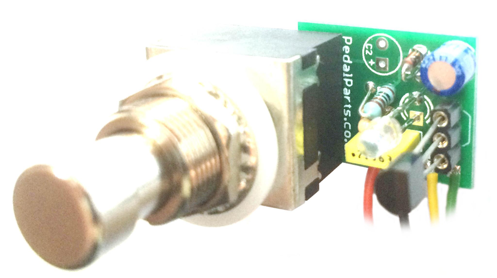
This neat little circuit replaces a decoupling capacitor on many PT2399-based delays to enable a Tails function, meaning your repeats are still heard after bypass without your current signal being delayed. Very simple to implement, and a tiny footprint meaning you should be able to fit it in...

shop.pedalparts.co.uk
This neat little circuit replaces a decoupling capacitor on many PT2399-based delays to enable a Tails function, meaning your repeats are still heard after bypass without your current signal being delayed. This has been available for some time as a tiny additional PCB, but implementing it could...
shop.pedalparts.co.uk
Of course, you could just McGyver something from examining the Fuzzdog Tails/TrueTails build-docs and not spend money on the PCB.
Look around
DIYSB and
FreeSB for more how-tos.
I like the TrueTails style, that way you can have true-bypass when you want/need it and tails when you...
...want...
...need...
...it...
t
However, there may be some feedback or phase cancellation. Maybe take the output from the FV-1's pin that outputs the repeats only. Consult the
FV-1 Datasheet PDF, I'm by no means an expert on any of this, let alone FV-1.


")

