What’s on *YOUR* workbench?

That should be an ON/OFF/ON, no connection in center position.
Nope, this is the switch that came with the pedal (I desoldered it). I send Keeley a message as well, to be sure, because it's such a strange little thing. I took it out, because I need a dual pole version of this to use two of these boards at the same time.

It's one of these:

x.png
 
Does one connection go to ground?
Hmm, each of the three wires has (with varying resistances) continuity with both ground and power. Measured at the jacks and the DC jack, as a double check. This is an FV-1 based circuit. Can this explain why these switches are set up like this?

I suppose buying or frankensteining the switch I need will be all it takes. I am just curious why it doesn't work the way I expect it to (like, through winding the wires together, to make the same connections as the switch would).
 
Last edited:
Nope, this is the switch that came with the pedal (I desoldered it).

That's odd, I've traced a few of the Keeley FV-1 pedals and can't say I've ever seen one of those.

That's the program select switch for the FV-1 IC right? If so you could rearrange the programs around on the EEPROM and use a more common switch.


Can this explain why these switches are set up like this?

I suppose buying or frankensteining the switch I need will be all it takes. I am just curious why it doesn't work the way I expect it to (like, through winding the wires together, to make the same connections as the switch would).

Normally you use an ON/OFF/ON, connect the center lug to a common point (3.3V or GND), and the outer two lugs to S0 and S1 of the FV-1 IC.

The program is selected by pulling S0 and S1 high or low in different combinations.

There's no need for a non-standard switch like that, I can't imagine any reason Keeley would have done it other than just having a bunch of them on hand.
 
Last edited:
That's odd, I've traced a few of the Keeley FV-1 pedals and can't say I've ever seen one of those.

That's the program select switch for the FV-1 IC right? If so you could rearrange the programs around on the EEPROM and use a more common switch.

One lug of the toggle switch might be going to 3.3V. Take a look at the Pythagoras schematic for an example of how the program switch might work.
I suspect all of Keeley's "studio pedals", 30ms, Abbey, and Memphis Sun, use this type of switch, so a custom order is likely. Haven't been able to find one online. It's indeed the program switch, which explains why it can function with such a strange switch configuration. Ah well, a solution will present itself undoubtly!
 
Last edited:
My guess is that maybe it was damaged when desoldering and that's why it's reading weird.

The switch is selecting between programs 0, 1, and 2 of the FV-1 IC.

If it were ON/ON/ON it would be selecting between 1, 2, and 3. Since connecting all three wires together didn't work, that indicates there is no program loaded into slot 3.

Probably a miscommunication/misunderstanding with Keeley. I'm pretty sure all of these use the same PCB with a few optional/alternate components.
 
Recorded a tiny demo of the Fuzz Cadet (I just ripped the original guitars out from a live recording and did mine instead, everything else is original), although it's not maybe the strongest suit of this pedal - had to use the neck pickup on my strat with the tone rolled down to around half. Although maybe a guitar with darker humbucker pickups might be able to pull it off without being so drastic with the tone control.

Edit: Forgot to mention UV led as is fitting for the dark arts.


DSC_3417.JPG DSC_3421.JPG
 
Last edited:
I believe UV LEDs are bad for your eyes. Be careful haha.

It turned out awesome :)
I actually looked into it when I first started using them - from what I read, too much UV light (from LED's or UV lightstrips, or obviously the sun) basically causes snowblindness-type symptoms. So your eyes get sore, swollen and irritated.

That is to say, you will know if you get symptoms from UV light, it doesn't do any secret damage. And I've never had any from using it as a pedal bypass LED. So I'm sure it is harmless, but obviously YMMV. You might get something if you stare right at it from up close for a long time, but it's on the floor and I'm not looking at it (plus I sanded it to get the diffused effect so it's not blaring at your eye annoyingly).

Now, if you use some stronger UV lights you might have to be very careful https://www.dazeddigital.com/life-c...-blinded-by-uv-light-at-apefest-nft-hong-kong

But a single LED is fine.
 
Final results from my big tag batch.

Rounded the corners and applied some black lacquer crayon. In the past I’ve shaved the lacquer off the high spots with a razor blade, but that didn’t work out great with the pitting on these ones so I mostly stripped it back off. I tried to leave just enough around the edges to highlight the letters/ make them look dirty.

Being out of tags has been my main excuse for not building pedals lately, so hopefully production will ramp up a bit.
BA3484F4-D0D7-4A37-9C8A-1BA9B5B2E55B.jpeg
DD4D1B6B-2A55-454E-8BF6-E9DEC9208EA8.jpeg
 
IMG_20240710_214237.jpg
Well, off the bench now. My first kit build and weird shaped guitar. Wasn't too hard after many years of fixing the damn things. Learned a lot about finishing though. Crazy I managed to make basswood look like mahogany. Stain, boiled linseed oil, shellac and poly. Now for the ridiculous case hunt.
 
Getting a little better each time.
This one was PnP with lye. Etch was shallow som lost some paint. Particularly Ash's head. :( 
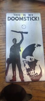
And the S in "IS" turned into a 6.
Not really going for amazing looking stuff. More just throwing graphics together for boards that are populated to get some practice.
Start to finish on this was about 2.5 hours, so getting faster with Illustrator. :)
1000004748.jpg 1000004749.jpg
1000004752.jpg
 

Attachments

  • 1000004750.jpg
    1000004750.jpg
    199 KB · Views: 3
Back
Top