What’s on *YOUR* workbench?

You, sir, are a complete madman and I applaud your efforts. I can't even imagine wiring up any of this stuff. I think you may have officially outed me as "old". Damn, when did I lose the desire for 20 tones :cry:
Haha I’m praying there’s no issues when I fire up that pedal and it works well. Took my time with the build for sure.

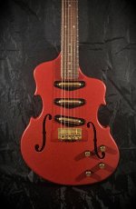
And I definitely don’t need 20 tones but figured why not hear what each pickup is capable of 😂
As you can see I’m a sucker for versatility, even if I end up setting something one way and leaving it.
 
Working on a MIDI controller using an Arduino Micro Pro. 6 banks with 6 possible buttons each and 2 expression pedal input jacks. The 7-segment shows the active bank and the LEDs show the latching state of each when latching is enabled. I still have some of the software side to sort out, but the hardware is good to go. I was also happy to finally find a use for the the long enclosure that came in my SmallBear mystery box a few years ago.

PXL_20240714_185045104.MP (1).jpg
 
D20D6D44-123F-4FFC-9A3D-C4E3038188DA.jpeg

I tried tracing this previously, months ago, but was unable to focus on it. Today, however...

Sick, 🤧 and while still in bed for most of the day, I again tried to trace the LP Vong and draw a schematic direct to DIYLC.
Alas I kept getting muddled with what was connected to what, and quickly tired of using my iPhone as a magnifier.

A few minutes at the bench, came up with colour-coding a copy of the PCB, and boom, while still in shock...

Back in bed; will transfer my colour-coded diagram to a proper schematic — if I can stay awake long enough. 🥱
 
How about what's in the workbench?
Got a new bench amp and decided to position it on the back left corner. Well, I don't want one more cable on the bench. Oh. And my bench is a recycled commercial door(out of an old Blockbuster). It's huge and heavy. Makes a great bench top -- and free(pulling it out of the dumpster was a b*tch!)
So anyway:
2024-07-1520.05.018275689446571361552.jpg
Jammed this guy in the previous bolt hole. Grabbed some shielded 2 wire that I got from Chaney for $2 and a $2 tayda TS jack and Bob's your auntie. I wasn't going to use my good cable for this if I didn't have to...
Anyway. It's stupid but practical.
 
Further to the LP VONG posted above, the HP VONG was pretty much the same layout and so went very quickly tracing it.
I'm really liking the colour-tracing method, and will continue to use it as I further streamline how I trace circuits.

After crashing for a while, I did two draughts of the LP schematic, the second being cleaner and is the keeper.

Realised I posted the LP Vong pic before the final step, it's missing the output. IF anybody cares to make their own schematic from the pic, OUT goes from the jack-pad lower-left and is connected to the right side of the 100k right below it.

Now to draught the HP schematic; should go more quickly as I can follow the skeleton of the LP schematic.


Oh, and the convertible-latch repair mentioned earlier has yet to be tested, as it rained just before we left for the car show, and somehow managed to dodge scattered showers all day! Great cars, great show.
However, the number of people sneezing at the event... well that's where I picked up this cold, I'm sure.
 
First time using my breadboard! Listening to some amazing classical guitar, through the Memphis Sun.

Needed the PCB jacks so soldered these off... And went at the pots while I was at it. Then came to the conclusion that wiring these switched jacks internally in a combo box is going to be more of a pain than I initially thought.

At least the circuit still lives! But not without wounds. Stupid solder pads were in a hurry to fly off the board. 😅

DSC_1197.JPG

Ana Vidovic's Concert
 
Last edited:
First time using my breadboard!
Congrats on getting your first breadboard circuit working!
As a heads-up, jamming those pots into your breadboard can screw up the internal contacts. They're tiny leaf spring type contacts and the legs of 16mm pots are to large for them and can deform them.
There are a handful of methods to interface pots. Look around the forum and see what solution others have used. I've grown partial to these trimmers personally.
Of course, do as thou wilt but it can be frustrating working with a deformed breadboard.
Helpful, as always! Thanks, I'll look into those. :) Something indeed felt off when pushing those into the breadboard...
 
Feeling good about yesterday's progress, I went at the Dimension C (WAZA) and was happy to learn that the Boss' loathed auto-on is going to be a huge convenience when I go box this with my dual low tide, as it's going to need a 4PDT, because I want to put an orderswitch between these units. No need to mess with the relay! Stereo analog dry through circuit is already done, but the Low Tide is going to take quite a while still due to the parts needed and ordered all over the place.

I love how I can live with buying battered / tortured pedals when taking this route!

I've also been thinking of contacting builders if they might just sell me circuit boards without all the bells and whistles I don't need (enclosure, all the to-be-soldered things, really).

And I was also, also thinking about swapping the selector's red SMD LEDs with white ones, but after yesterday's hassle with lifting pads and traces and whatnot, I'm just going to learn to live with stock color. 😅

IMG_20240717_202643.jpg
 
Last edited:
Excited to share some demos of the nearly complete FUZZILLA VS AKHIBARA - high gain highly variable fuzz. Demos of the fuzz side - Germanium Radiation (4.5 Ge transistor fuzz) and Atomic Breath (octave up). Waiting on a matched pair of JFETs for the Nuclear Pulse (phase 45) side courtesy of @bean 😄

This thing sustains for days and has unlimited gain on tap. Circuit based on modified Park Sound fuzz/Tonebender MKIII.

Germanium Radiation: high gain fuzz stacked with 4.5 Toshiba 2SA478 Ge transistors found on my search in Akhibara Tokyo. (.5 because of extra one used as Ge diode)
Pots: Fuzz, Tone (DBA Fuzz War style), Charge (alternative gain control going into later gain stages), Volume
Switches: Meltdown (adds 4th Ge transistor gain stage), Isotope (switch between 5th 2SA478 used as Ge diode clipping vs CBS 1N69), Fission (tone bypass), Decay (voltage starve to transistors)

Overview:
Guitar volume clean-up:
Decay/gated fuzz to High gain chug:
 
Back
Top