The 4pdt switch is like 4 independent spdt switches side by side. The middle lug will connect with the top or bottom row when switched. @Feral Feline has a lot of drawings about how to use switches.
I am having a hard time imagining the use case for a balanced in/balanced out pedal, especially one that would need a true bypass. Please tell us more.
So... you'll need to read up on switches.
I thought I'd post this in the thread instead of in a DM; as this may be of benefit to others new to arcane idiosyncrasies of switchery.
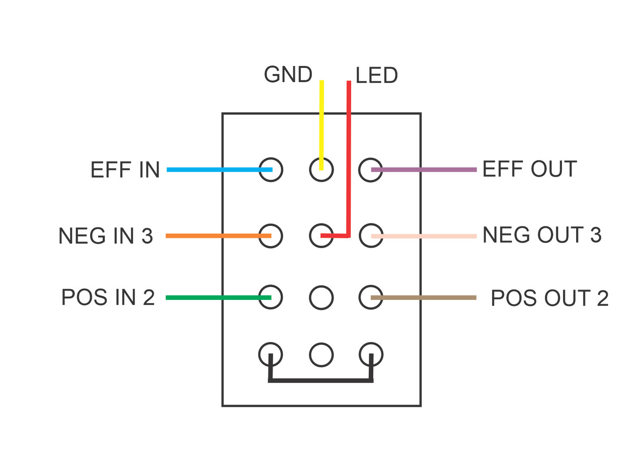
Using the same orientation of the switch in the OP, this is how it would be making the connections:
I've split up the 4PDT into its individual poles using the thin pink lines, as per Nic's post (#4), think of a 4PDT as 4 x SPDT.
The pink arrows show what's connected when the toggle is flipped one way or t'other (note how the connections are opposite the way the red-topped toggle points).
The middle lug of each pole is the COMMON. So you can see the first pole either EFF IN or EFF OUT are connecting to ground; and your 4th pole, the bottom with the jumper, isn't connected to anything external and does nothing relevant to your needs. It would be this 4th pole that you'd want to use for your LED, but if pressed into service for some other use ... since you just need a toggle, you may find the luxury of LED-indication gets superseded for some other more pertinent function.
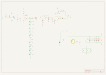
Most often, a switch is depicted with the poles vertical, not horizontal — as per Jimilee's post (#2):
For this current project, we need only concern ourselves with the "4PDT on/on" in the above graphic.
If I understand your needs correctly, you basically are wanting a true-bypass for an XLR connection.
We don't need to switch ground out, so we're looking at switching two signals, not three as per your 4PDT diagram.