Yep, Barry is correct.
The text actually should read "4.5 - 5V" and "4.5 - 5.2V" respectively.
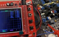
The original used fixed resistors, not trim pots, but the actual voltage measured on the Collector of Q1 and Drain of Q5 was 4V. The measurements were taken while powered on a 9V supply.